A hydraulic bidirectional mud pump for preventing clogging in oil exploitation
An oil extraction and anti-clogging technology, which is applied to the components of pumping devices for elastic fluids, piston pumps, and variable displacement pumps, etc. running effect
- Summary
- Abstract
- Description
- Claims
- Application Information
AI Technical Summary
Problems solved by technology
Method used
Image
Examples
Embodiment 1
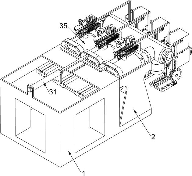
[0037] A hydraulic two-way mud pump used for anti-clogging in oil production, such as Figure 1-7 As shown, it includes a cavity chassis 1, a special-shaped connecting frame 2, a reciprocating pumping mechanism 3, a one-way conduction mechanism 4, and an anti-blocking mechanism 5. The left side of the cavity chassis 1 is fixedly connected with a special-shaped connecting frame 2, and the special-shaped connection The frame 2 is provided with a reciprocating pumping mechanism 3, the reciprocating pumping mechanism 3 is located above the cavity chassis 1, the left side of the special-shaped connecting frame 2 is fixedly connected with a one-way conduction mechanism 4, and the left part of the one-way conduction mechanism 4 is provided with Anti-clogging mechanism5.
[0038] The reciprocating pumping mechanism 3 includes an electro-hydraulic push rod 31, a triangular push rod 32, a special-shaped connecting plate 33, a piston body 34, and a piston rod 35. 31 is fixedly connected...
Embodiment 2
[0043] On the basis of Example 1, such as Figure 8-14 As shown, a rotating mechanism 6 is also included, and the rotating mechanism 6 is located above the special-shaped connecting frame 2. The rotating mechanism 6 includes an L-shaped opening support frame 61, a push ball rod 62, a third return spring 63, a rectangular slotted frame 64, Round head shaft frame 65, dial 66 and cam 67, the top of piston rod 35 is fixedly connected with L-shaped opening support frame 61, and the L-shaped opening support frame 61 is slidably connected with three push rods 62, which promotes the ball rod 62. A third return spring 63 is connected between the L-shaped opening support frame 61, the third return spring 63 is used to drive and push the club 62 to reset, and the top of the push club 62 is fixedly connected with a rectangular slot for driving the dial 66 to rotate Frame 64, three round head rotating shaft frames 65 are fixedly connected on the L-shaped opening support frame 61, and the r...
Embodiment 3
[0048] On the basis of Example 2, such as Figure 15-16As shown, a mud pushing mechanism 9 is also included, and the mud pushing mechanism 9 is located below the anti-clogging mechanism 5. The mud pushing mechanism 9 includes a T-shaped slotted frame 91, a special-shaped pushing plate 92, a first return spring 93, a sliding rack Frame 94, the second homing spring 95, double-sided wedge block 96, the 3rd homing spring 97, L-type rotating shaft frame 98, gear one 99, gear two 910, mobile rack frame 911, movable gear block 912 and the fourth Returning spring 913, T-shaped slotted frame 91 is fixedly connected to the bottom of chamber communication valve 51, and special-shaped push plate 92 is slidably connected to T-shaped slotted frame 91, between T-shaped slotted frame 91 and special-shaped push plate 92 Fixedly connected with a first return spring 93, the first return spring 93 is used to drive the special-shaped push plate 92 to reset, and the cavity communication valve 51 is...
PUM
 Abstract
Description
Claims
Application Information
 - R&D
- Intellectual Property
- Life Sciences
- Materials
- Tech Scout
- Unparalleled Data Quality
- Higher Quality Content
- 60% Fewer Hallucinations
Browse by: Latest US Patents, China's latest patents, Technical Efficacy Thesaurus, Application Domain, Technology Topic, Popular Technical Reports.
© 2025 PatSnap. All rights reserved.Legal|Privacy policy|Modern Slavery Act Transparency Statement|Sitemap|About US| Contact US: help@patsnap.com


