
Mobile charging system and mobile charging positioning method

A mobile charging and charging pile technology, which is applied to electric vehicle charging technology, charging stations, electric vehicles, etc., can solve the problems of damaged charging pairing structure, docking accuracy cannot meet the requirements, and charging piles cannot be used universally. The effect of precision requirements

Pending Publication Date: 2021-08-17
广东塔斯克机器人有限公司
View PDF0 Cites 0 Cited by
  • Summary
  • Abstract
  • Description
  • Claims
  • Application Information

AI Technical Summary

Problems solved by technology

If the position of the charging pile moves during use, it may cause the docking accuracy to fail to meet the requirements and damage the charging pairing structure
In addition, for applications where multiple vehicle types are mixed, due to the inconsistent distance between the ground code recognition lens and the charging connector on the vehicle, the distance between the ground code of the charging station and the charging pile also needs to be laid at different values, making the charging pile unable to be used universally.

Method used


Image

  • Mobile charging system and mobile charging positioning method
  • Mobile charging system and mobile charging positioning method
  • Mobile charging system and mobile charging positioning method

Examples


Embodiment Construction

[0039] The present invention will be described in detail below in conjunction with the accompanying drawings and specific embodiments, wherein the schematic embodiments and descriptions are only used to explain the present invention, but not as improper limitations to the present invention.

[0040] It should be noted that, in the case of no conflict, the embodiments in the present application and the features in the embodiments can be combined with each other. The present invention will be described in detail below with reference to the accompanying drawings and examples.

[0041] It should be noted that the terminology used here is only for describing specific implementations, and is not intended to limit the exemplary implementations according to the present application. As used herein, unless the context clearly dictates otherwise, the singular is intended to include the plural, and it should also be understood that when the terms "comprising" and / or "comprising" are used ...


PUM


Abstract

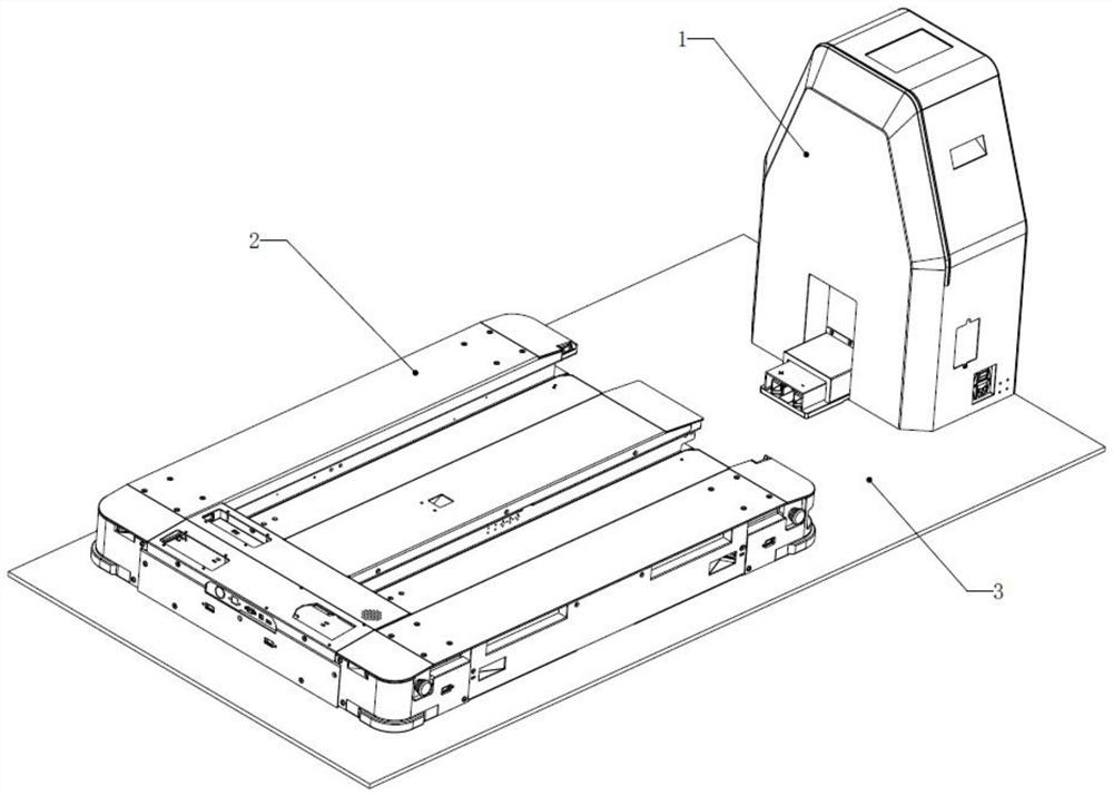
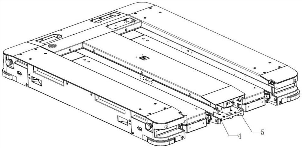
The invention discloses a mobile charging system and a mobile charging positioning method. The mobile charging system comprises a mobile body and a charging pile, wherein a driving assembly is arranged on the movable body so as to enable the movable body to move freely. The mobile charging system further comprises a charging port, a power supply port, a pattern recognition module, a positioning image and a control module, wherein charging port is formed in the mobile body, and the power supply port is formed in the charging pile; the pattern recognition module and the positioning image are separately arranged on different equipment, and the pattern recognition module is right opposite to the positioning image to recognize information of the positioning image; and the control module is used for adjusting the relative movement direction of the mobile body and the charging pile according to the information of the positioning image so as to enable the charging port and the power supply port to be effectively butted for charging within the tolerance range. According to the charging positioning method, charging is completed through image matching. According to the invention, a charging position ground code is canceled, so that the mounting precision of the charging pile is reduced; the charging pile is recognized and positioned through a sensor, and multiple vehicles can share the charging pile; and the mobile body can carry out position correction in real time during charging butt joint.

Description

technical field [0001] The invention relates to the charging field, in particular to a mobile charging system and a mobile charging positioning method. Background technique [0002] At present, mobile robots on the market will automatically search for charging piles to charge when they are idle or when the power reaches the design threshold. Since the front of the car is equipped with navigation devices such as laser scanners, the charging port on the car end is generally arranged at the rear of the car body. A ground code will be laid on the walking path of the AGV in front of the fixed position of the charging pile. After identifying the ground code, the AGV will back up to the charging position to complete the charging docking. In the current charging and docking scheme, ground yards need to be laid on the stop position of the AGV in front of the charging pile, and the position accuracy of the ground yard and the charging pile needs to be guaranteed, so the requirements f...

Claims


Application Information

Patent Timeline
IPC IPC(8): B60L53/14B60L53/35B60L53/31
CPCB60L53/14B60L53/31B60L53/35Y02T10/70Y02T10/7072Y02T90/12Y02T90/14
Inventor 不公告发明人
Owner 广东塔斯克机器人有限公司
Learn More