
Storage device and drawer closing method thereof

A technology for storage devices and drawers, which is applied to drawers, household utensils, furniture parts, etc. It can solve the problems of lack of cushioning, damage to drawers, and large impact force, so as to avoid hard collision, avoid position deviation, and ensure effective opening and closing Effect

Pending Publication Date: 2021-08-17
SUZHOU KIMAUTO TECH CO LTD
View PDF4 Cites 0 Cited by
  • Summary
  • Abstract
  • Description
  • Claims
  • Application Information

AI Technical Summary

Problems solved by technology

[0004] In the first type of motor-driven structure, when the drawer needs to be closed after opening, the trigger signal is usually generated by the button to start the motor to drive the drawer to close. This method is not convenient for operation, and the setting button also increases The complexity of the control structure is eliminated; more importantly, in this structure, when the drawer is open, if there is no close signal, the drawer cannot be closed automatically. If the staff in front of the drawer accidentally collides with the drawer, the There is a lack of buffer between the two, which is likely to cause injury to the staff and damage to the drawer, and the safety needs to be improved
[0005] In the second structure driven by magnetic force, although this structure can have a certain buffering effect and avoid the safety problems caused by the abnormal collision between the staff and the opened drawer, this structure, due to the use of magnetic force to open and close, the drawer switch When the impact force is relatively large, it is easy to make the items stored in the drawer vibrate greatly, causing the items to be confused and affecting the safety of the items in the drawer. difficult to apply

Method used

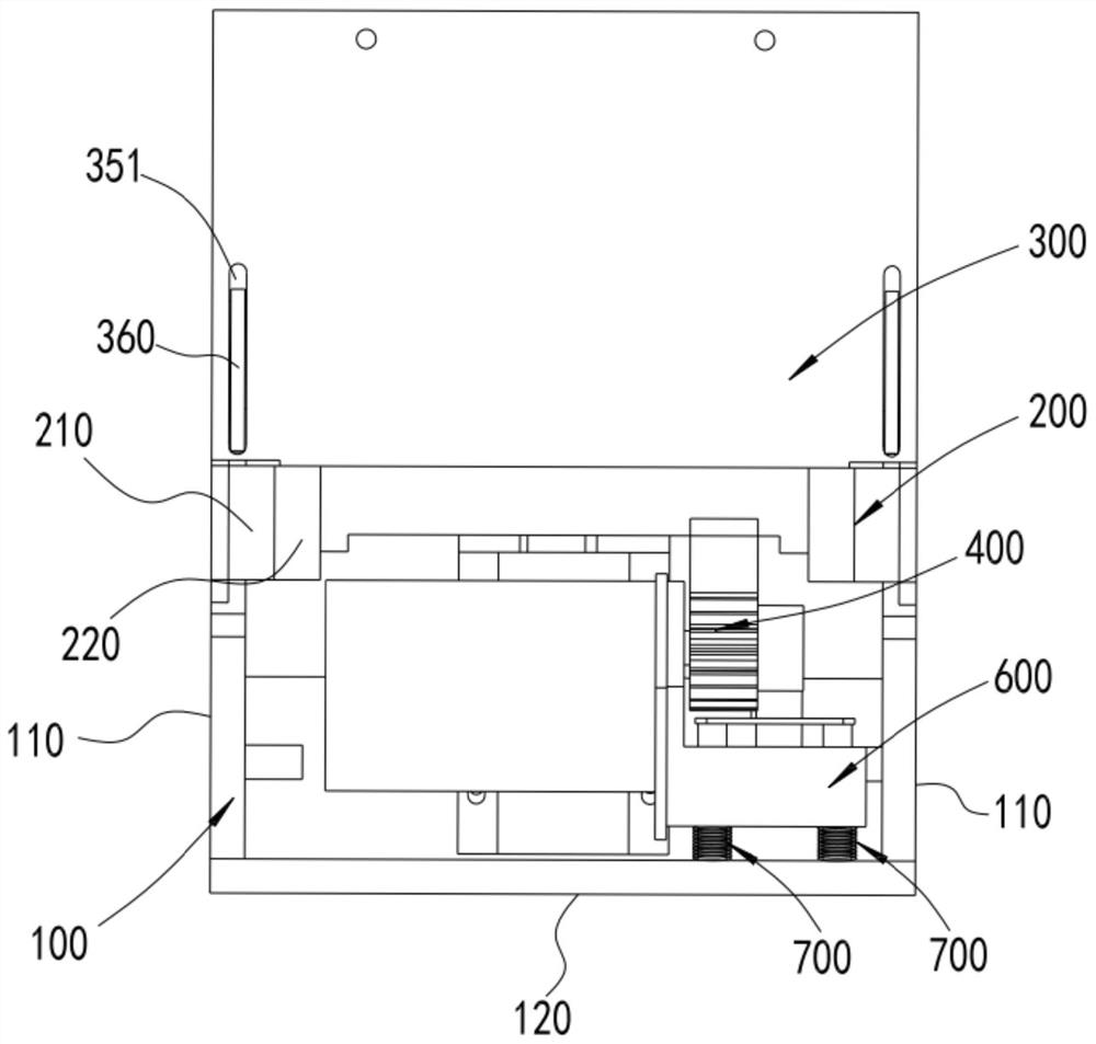
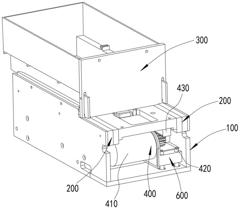
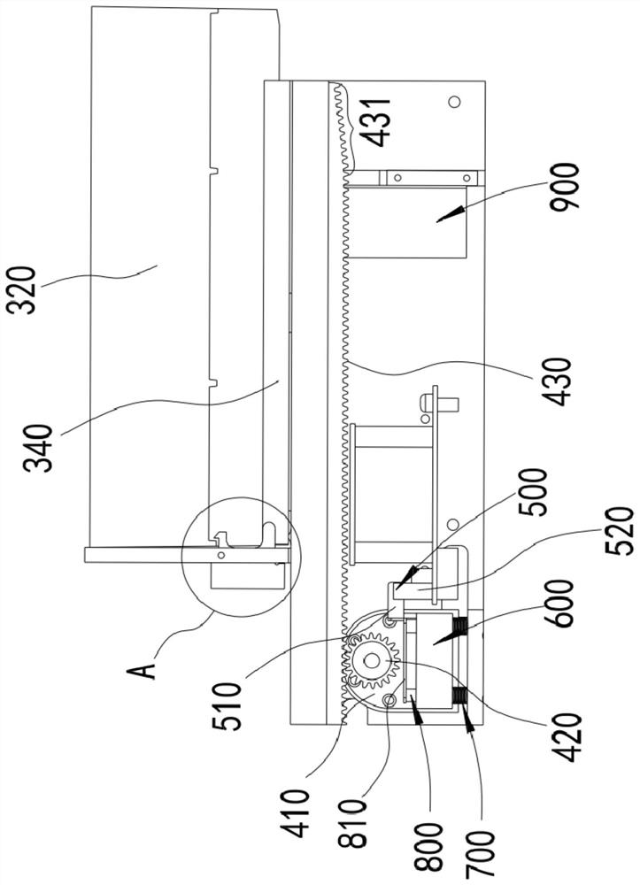

Image

  • Storage device and drawer closing method thereof
  • Storage device and drawer closing method thereof
  • Storage device and drawer closing method thereof

Examples


Embodiment Construction

[0040] Objects, advantages and features of the present invention will be illustrated and explained by the following non-limiting description of preferred embodiments. These embodiments are only typical examples of applying the technical solutions of the present invention, and all technical solutions formed by adopting equivalent replacements or equivalent transformations fall within the protection scope of the present invention.

[0041] In the description of the scheme, it should be noted that the terms "center", "upper", "lower", "left", "right", "front", "rear", "vertical", "horizontal", " The orientation or positional relationship indicated by "inner", "outer", etc. is based on the orientation or positional relationship shown in the drawings, and is only for the convenience of description and simplification of description, rather than indicating or implying that the device or element referred to must have a specific orientation , constructed and operated in a particular or...


PUM


Abstract

The invention discloses a storage device and a drawer closing method thereof. According to the storage device, one of a motor or a rack for driving a drawer is arranged on an installation base, the installation base is arranged on an energy storage mechanism, when the drawer is opened, a gear and the rack are unhooked, and the installation base is located at a high position; when the gear and the rack are meshed, the installation base is located at a low position; a position detection device is combined to determine the position of the installation base; when the installation base is in the low position, the motor is controlled to be started to enable the drawer to be automatically closed; and when the drawer needs to be closed, pushing force only needs to be applied to any position of the front end of the drawer, compared with pressing of a button at a specific position, operation is easier, and the storage device is more suitable for pharmacy application. Meanwhile, when a worker in front of the drawer collides with the opened drawer, the drawer can automatically trigger the motor to close the drawer under the action of thrust, so that hard collision between the drawer and the worker is effectively avoided, and the safety is fully improved.

Description

technical field [0001] The invention relates to the field of medical equipment, in particular to a storage device and a drawer closing method thereof. Background technique [0002] A drawer is a box for storing things. It has a bottom and no cover, and can be pulled out and pushed in. [0003] Conventional drawers are opened and closed by manual pulling. In some automated pharmacies, automated drawers are required to facilitate automatic medicine taking. Conventional automated drawers use a driving mechanism to drive the drawer to open and close automatically. For example, the application number is 201621463222 . 8. The structure disclosed in 201710396978.8. [0004] In the first type of motor-driven structure, when the drawer needs to be closed after opening, the trigger signal is usually generated by the button to start the motor to drive the drawer to close. This method is not convenient for operation, and the setting button also increases The complexity of the control ...

Claims


Application Information

Patent Timeline
IPC IPC(8): A47B88/40A47B88/457A47B88/919
CPCA47B2210/09A47B88/40A47B88/457A47B88/919
Inventor 董振海
Owner SUZHOU KIMAUTO TECH CO LTD
Learn More