System for measuring periodontal pocket depth

A periodontal pocket and depth technology, applied in the field of tooth measurement, can solve problems such as insufficient lighting to accurately and quickly read the color and scale of the periodontal probe tip, human error, and time-consuming process

Active Publication Date: 2021-08-13
3SHAPE AS
View PDF5 Cites 0 Cited by
  • Summary
  • Abstract
  • Description
  • Claims
  • Application Information

AI Technical Summary

Problems solved by technology

[0005] A significant disadvantage of periodontal probes discussed previously involves the difficulty dentists have in reading the color coding or scale once the probe is positioned between the tooth and gum
Overhead dental lights can be used, but this arrangement does not provide sufficient illumination for accurate and quick reading of the colors and scales present on the probe tips of periodontal probes
In addition, depth measurements may also be affected by the force exerted on the probe tip when it is inserted into the pocket, thus making this measurement dependent on the skill and experience of the user
Finally, depth measurements may have to be manually entered into patient records
Such manual entry not only makes the process time-consuming and cumbersome, but also prone to human error

Method used


Image

  • System for measuring periodontal pocket depth
  • System for measuring periodontal pocket depth
  • System for measuring periodontal pocket depth

Examples


Embodiment Construction

[0125] In the following description, reference is made to the accompanying drawings, which show by way of illustration how the invention may be practiced.

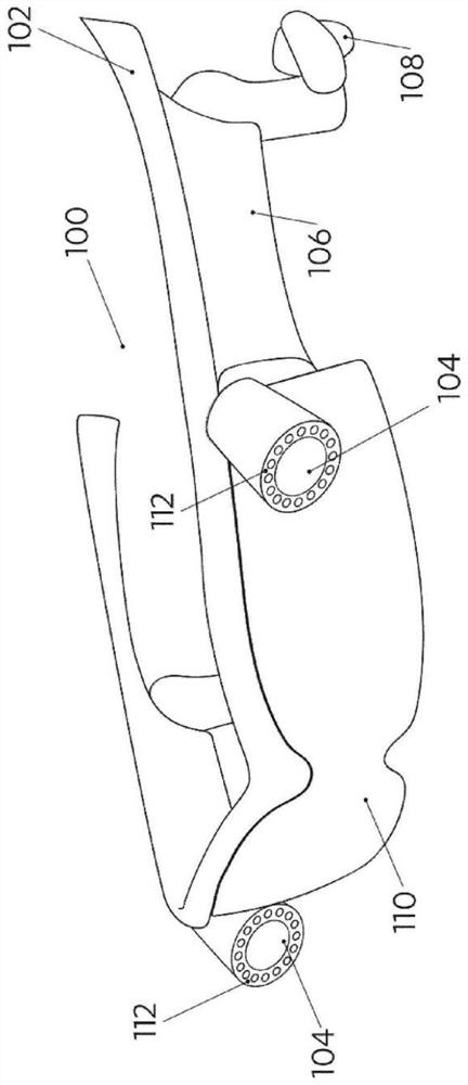
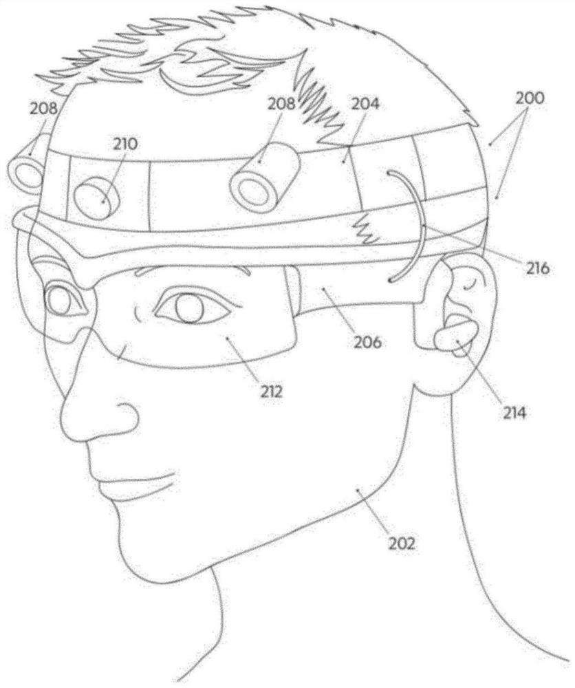
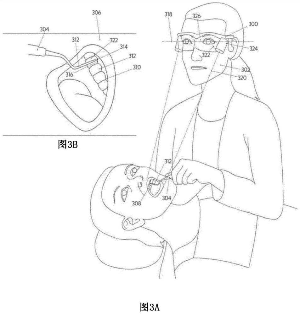
[0126] figure 1 A system according to an embodiment is shown. System 100 includes a frame 102 , at least one camera 104 and a processor 106 . The framework is configured to be configured by the user (202, figure 2 ) to wear. At least one camera 104 is attached to the frame 102 and is configured to capture at least one 2D image ( Figure 3B or Figure 6B ). The at least one 2D image includes at least a portion of the tooth (322, FIG. 3 ), a gingival margin (316, FIG. 3 ) defined by a portion of the gingiva (310, FIG. 3 ) adjacent to at least a portion of the tooth, and when the probe tip is positioned (312, FIG. 3) Representation of the probe tip when inserted into the periodontal pocket (412, FIG. 4; 512, FIG. 5). Processor 106 is configured to receive the captured at least one 2D image. The processor is further c...


PUM


Abstract

According to an embodiment, a system for measuring a depth of a periodontal pocket defined by a gap between a tooth and gingiva is disclosed. The system includes a frame, at least one camera, and a processor. The frame is configured to be worn by a user. The at least one camera is attached to the frame and configured to capture at least one 2D image of an intraoral target area. The at least one 2D image includes a representation of at least a part of the tooth, a gingiva margin defined by a section of the gingiva adjacent to the at least a part of the tooth, and a probe tip when the probe tip is inserted into the periodontal pocket. The processor is configured to receive the captured at least one 2D image. The processor is further configured to determine, in relation to the gingiva margin, an insertion length of the probe tip in the periodontal pocket by applying an image processing technique on information obtained about the probe tip in the captured at least one 2D image. The determined insertion length represents the depth of the periodontal pocket.

Description

technical field [0001] This disclosure relates to dental measurements. In particular, the present disclosure relates to methods and systems for automatically measuring periodontal pocket depth, ie, the depth of the pocket between the gum and the tooth. Background technique [0002] Periodontal pocket depth, also known as the gingival sulcus, is measured from the gingival margin (the top of the gum) to the epithelial attachment (the point where the gum attaches to the tooth), which forms the bottom of the pocket. Gingival recession has been described as apical migration of the gingival margin such that the gingival margin gradually moves away from the cementum-enamel junction, thereby exposing the root surface to the oral environment. Gingival recession is usually measured as the distance between the receded gingiva and the cementum-enamel junction. Loss of attachment included periodontal pocket depth and gingival recession measurements. In the absence or absence of gingiv...

Claims


Application Information

Patent Timeline
Patent Type & Authority Applications(China)
IPC IPC(8): A61C19/04
CPCA61C19/043A61B1/247A61B1/04A61B1/00009A61B1/24G06T2207/30036H04N13/207G06T7/55
Inventor 迈克·范德普尔A·比尔克M·温瑟S·S·帕蒂尔S·F·托夫斯基
Owner 3SHAPE AS
Why Eureka
Try Eureka