A wind turbine wind wheel variable pre-cone angle device and using method

A technology of wind turbines and pre-cone angles, which is applied to wind turbines, wind power generation, and wind turbines in the same direction as the wind. It can solve problems such as reducing power generation, tower collisions, and blade deformation, and achieve reduced maintenance costs. The effect of increasing the service life

Active Publication Date: 2022-05-24
HUANENG CLEAN ENERGY RES INST
View PDF5 Cites 0 Cited by
  • Summary
  • Abstract
  • Description
  • Claims
  • Application Information

AI Technical Summary

Problems solved by technology

Because the pre-cone angle of the wind rotor of the conventional wind turbine is fixed, when the large-scale development of the wind turbine, the deformation of the long flexible blade tip of the large-scale wind turbine can reach 7-8 meters, if the design is too small to meet the clearance requirements, it will cause blade deformation and tower If the design is too large, it will affect the effective sweeping area of ​​the wind rotor and reduce the power generation

Method used


Image

  • A wind turbine wind wheel variable pre-cone angle device and using method
  • A wind turbine wind wheel variable pre-cone angle device and using method
  • A wind turbine wind wheel variable pre-cone angle device and using method

Examples


Embodiment 1

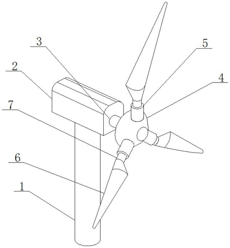
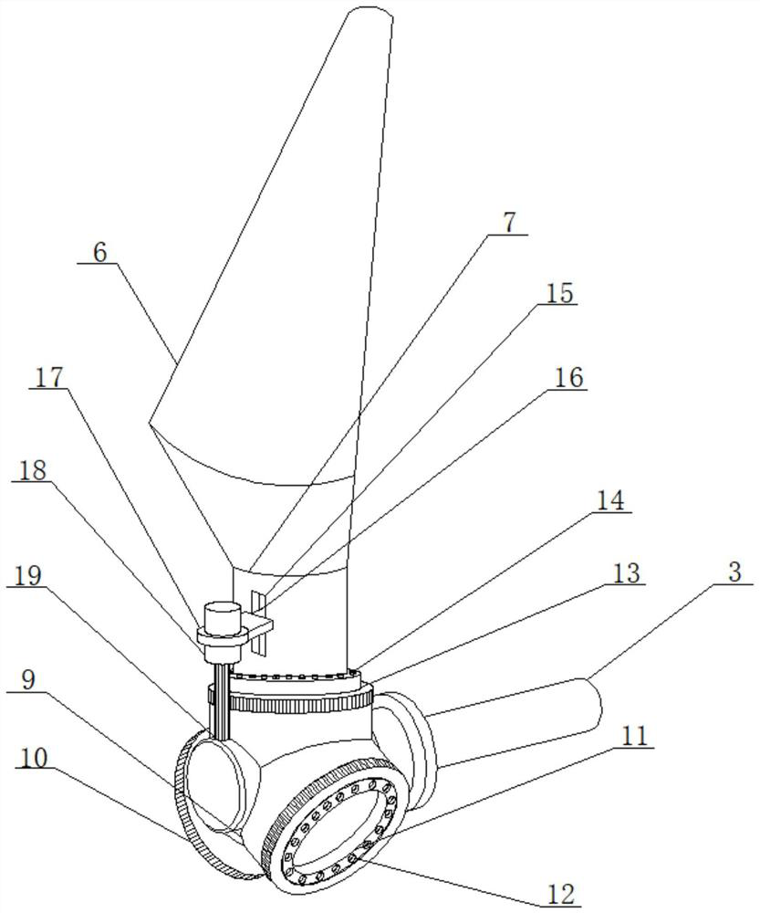
[0037] see Figure 1 to Figure 7 , the present invention provides a variable pre-cone angle device for a wind turbine of a wind turbine, comprising a tower 1, a nacelle 2 is installed on the top of the tower 1, a main shaft 3 is installed on the nacelle 2, and a connecting seat 9 is connected to the other end of the main shaft 3 The hub 4 is installed on the outside of the connecting seat 9, the hub 4 is connected with the blade root connecting section 5, the blade root connecting section 5 is connected with the blade root 7, and the blade root 7 is connected with the blade 6.

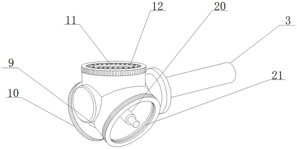
[0038] The connecting base 9 is arranged in a Y shape and includes three protruding posts 91 ; the three protruding posts 91 are evenly arranged, and the included angle between them is 120°. The top of the boss 91 is provided with a gear ring 10 , the inner wall of the gear ring 10 is provided with a fixing groove 21 , the pitch bearing 11 is installed in the gear ring 10 through the fixing groove 21 ,...

Embodiment 2

[0046] The present invention also provides a method for using the variable pre-cone angle device of the wind wheel of the wind turbine, comprising the following steps:

[0047] Step 1: Provide the required electrical energy to the internal electrical appliances through the power supply after the power generation is completed. After the installation of each equipment is completed, the blades 6 are rotated by the blowing of wind energy, and the rotation of the blades 6 makes the hub 4 and the main shaft 3 rotate. , so that the main shaft 3 converts the kinetic energy transmission into electrical energy for use.

[0048] Step 2: Adjust the pre-cone angle of the blade 6 according to different conditions. When in use, according to the different wind directions, start the motor 18 to drive the toothed roller 19 to rotate. The toothed roller 19 cooperates with the gear ring 10 and is dialed by the fixed plate 16 The moving blade root 7 makes the blade 6 rotate on the pitch bearing 11...


PUM


Abstract

The invention provides a variable pre-cone angle device for a wind turbine wheel of a wind turbine and a method for using it, including a connecting seat, a hub, a blade root and a blade; The blade root is connected to the blade root, and the blade is connected to the blade root; there are three bosses evenly distributed on the connecting seat; the top of the boss is provided with a gear ring, and a fixing groove is opened on the inner wall of the gear ring, and the pitch bearing is installed on the gear through the fixing groove. the blade root is fixed on the pitch bearing; the blade root has a slot, and a fixing plate is installed inside the slot, and the fixing plate is connected to the motor base located outside the slot, and the motor A motor is installed on the seat; the output shaft of the motor is connected with a toothed roller, and the toothed roller meshes with the gear ring. The invention can reduce the blade cone angle when the wind speed is small, increase the sweeping area, and improve the production efficiency; when the wind speed is high or the blade deformation is large, the blade cone angle can be increased to avoid the deformation of the blade and the tower hit and damage the device.

Description

technical field [0001] The invention belongs to the field of horizontal-axis wind turbine equipment, and particularly relates to a variable pre-cone angle device for a wind wheel of a wind turbine and a method for using the same. Background technique [0002] Energy is the main material basis of social economy and human life, and is the driving force for social development. However, the reserves of non-renewable energy sources such as oil, coal, and natural gas, which are the main pillars of the world's energy, are decreasing day by day. Many countries in the world are developing wind power generation. As a new energy source, wind power generation has formed a relatively mature scale. [0003] The wind wheel is one of the most important components for absorbing wind energy. The wind flows through the blade, and the surface of the blade is disturbed to form torque and thrust, and the blade deforms accordingly. When the wind speed changes, the torque changes and the blade cle...

Claims


Application Information

Patent Timeline
Patent Type & Authority Patents(China)
IPC IPC(8): F03D1/06F03D7/04
CPCF03D1/0658F03D1/0675F03D7/022F03D7/0224F03D7/042F05B2270/321Y02E10/72
Inventor 李媛蔡安民林伟荣张林伟郑磊许扬蔺雪峰
Owner HUANENG CLEAN ENERGY RES INST
Why Eureka
Try Eureka