
Method for transforming yarn spinning and/or twisting machine and modified yarn spinning and/or twisting machine resulting from said method

The technology of a kind of spinning machine, twisting machine, is used in the field that is used to transform yarn spinning machine and/or twisting machine and the improved yarn spinning machine and/or twisting machine obtained by above-mentioned, can solve Improve expensive, difficult to implement, etc.

Active Publication Date: 2021-07-30
特威斯特普非特公司 +1
View PDF18 Cites 0 Cited by
  • Summary
  • Abstract
  • Description
  • Claims
  • Application Information

AI Technical Summary

Problems solved by technology

[0012] The problem is that said improvement has so far been very expensive and difficult to execute, even if it is not as expensive as making a new machine, because, broadly speaking, it is Based on the "cutting" of the upper element of the machine covering the area of ​​the guiding and feeding means of the yarn, and by adding elements such as supports or others, such as bridge posts and bridge profiles, the upper element is positioned in the Increased higher position relative to the above distance of the twisting device

Method used


Image

  • Method for transforming yarn spinning and/or twisting machine and modified yarn spinning and/or twisting machine resulting from said method
  • Method for transforming yarn spinning and/or twisting machine and modified yarn spinning and/or twisting machine resulting from said method
  • Method for transforming yarn spinning and/or twisting machine and modified yarn spinning and/or twisting machine resulting from said method

Examples


Embodiment Construction

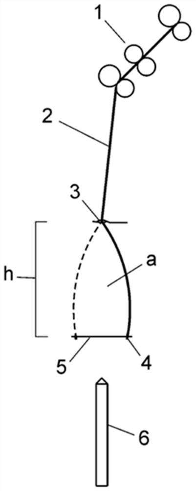
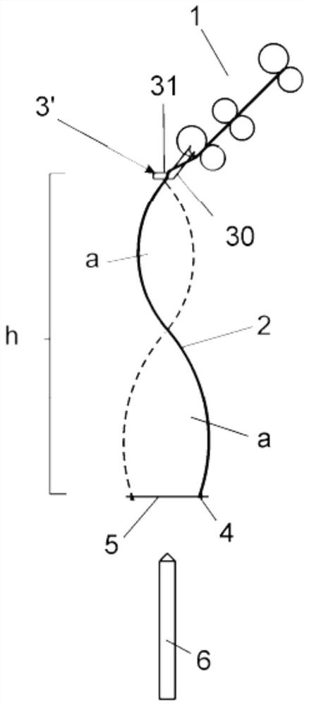
[0035] In view of the above figures, and according to the numbering adopted, in addition to examples of improved machines according to the prior art, there can be seen exemplary and non-limiting examples of twisting and / or spinning machines improved according to the invention The embodiment includes the parts and elements pointed out and described in detail below.

[0036] therefore, figure 1 The basic elements of an unmodified conventional ring-spun yarn twister and / or spinning machine are shown very schematically, that is to say it has only a single balloon area (a), which basically consists of the following elements Composition: yarn (2) feeding device (1), preferably a set of standard rollers; conventional guiding device (3), located at a certain distance below the feeding device (1) and delimiting said balloon above the upper end of zone (a); and the twisting device (4) and winding device (5) of said yarn (2) perpendicular to the pick-up spool (6), which is preferably co...


PUM


Abstract

A method for transforming a yarn spinning and / or twisting machine and the yarn spinning and / or twisting machine modified according to said method to increase the height (h) of the balloon region zone (a), between the upper and lower ends thereof, in order to provide said zone with two or more balloon regions (a), with means for feeding (1) the thread (2) using conventional upper guides (3), and means for tensing (4) and rolling (5) the thread (2) onto a lower collection reel (6), comprising: elimination of the conventional guide means (3); and the incorporation of an additional guide accessory (3') immediately after the feed means (1), consisting, for example, of a clip (30) or a set of rollers (32) optionally with a conveyor belt (33).

Description

[0001] purpose of invention [0002] As stated in the title of this specification, the present invention relates to a method for retrofitting a yarn twisting machine and / or spinning machine and a yarn twisting machine and / or spinning machine improved according to said method, The advantages and novel features described in detail below are provided and improvements to the prior art are presented for use in connection therewith. [0003] The object of the present invention is a yarn twisting and / or spinning machine modified to perform said yarn twisting and / or spinning by rotating the yarn with a plurality of balloon regions, comprising fittings that increase the height of the zone of the balloon area, i.e. make the gap between the guiding device in the feeding area of ​​the yarn and the twisting device for winding the yarn to the yarn of the pick-up spool The separation distance is increased, therefore, the basic aspect of the invention is a method for retrofitting a yarn twisti...

Claims


Application Information

Patent Timeline
Patent Type & Authority Applications(China)
IPC IPC(8): D01H7/52
CPCD01H1/02D01H13/04D01H7/52D01H1/42D01H2700/24
Inventor 艾伯特·加朗·利翁格拉斯乔迪·加朗·利翁格拉斯
Owner 特威斯特普非特公司
Learn More