
Circuit board with windproof constant temperature device

A constant temperature device and circuit board technology, which is applied in the direction of circuit devices, printed circuits connected with non-printed electrical components, circuit heating devices, etc., can solve the problem of poor constant temperature effect, influence on device performance, and poor thermal insulation performance of metal shells. Waiting for a question

Inactive Publication Date: 2021-07-30
CIG SHANGHAI
View PDF9 Cites 0 Cited by
  • Summary
  • Abstract
  • Description
  • Claims
  • Application Information

AI Technical Summary

Problems solved by technology

[0003] However, on the one hand, this method is greatly affected by other heating devices on the circuit board, that is, the heat emitted by other devices on the circuit board can be conducted to the sensitive device through the circuit board, causing the temperature of the tooth device to change, thereby improving the performance of the device. On the other hand, the heat preservation and heat insulation performance of the metal shell itself is not very good, that is, the thermal conductivity of the metal is good, and the temperature of the air outside the metal shell changes greatly, which will change the temperature of the metal shell and affect the temperature of the metal shell. air temperature inside the metal case, so that the device is affected
Especially for some devices with relatively high sensitivity and a small amount of heat generation or intermittent heat generation, the constant temperature effect of this method is even worse due to the heat generation of the device itself

Method used


Image

  • Circuit board with windproof constant temperature device
  • Circuit board with windproof constant temperature device
  • Circuit board with windproof constant temperature device

Examples


Embodiment Construction

[0041] The following will clearly and completely describe the technical solutions in the embodiments of the present invention with reference to the accompanying drawings in the embodiments of the present invention. Obviously, the described embodiments are only some, not all, embodiments of the present invention. Based on the embodiments of the present invention, all other embodiments obtained by persons of ordinary skill in the art without making creative efforts belong to the protection scope of the present invention.

[0042] In the following description, many specific details are set forth in order to fully understand the present invention, but the present invention can also be implemented in other ways different from those described here, therefore, the protection scope of the present invention is not limited by the specific implementation disclosed below. Example limitations.

[0043] In describing the present invention, it should be understood that the terms "center", "l...


PUM


Abstract

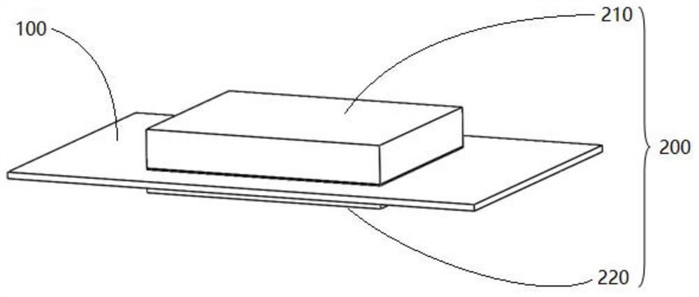
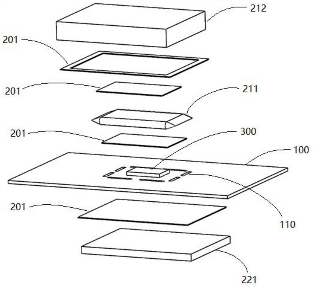
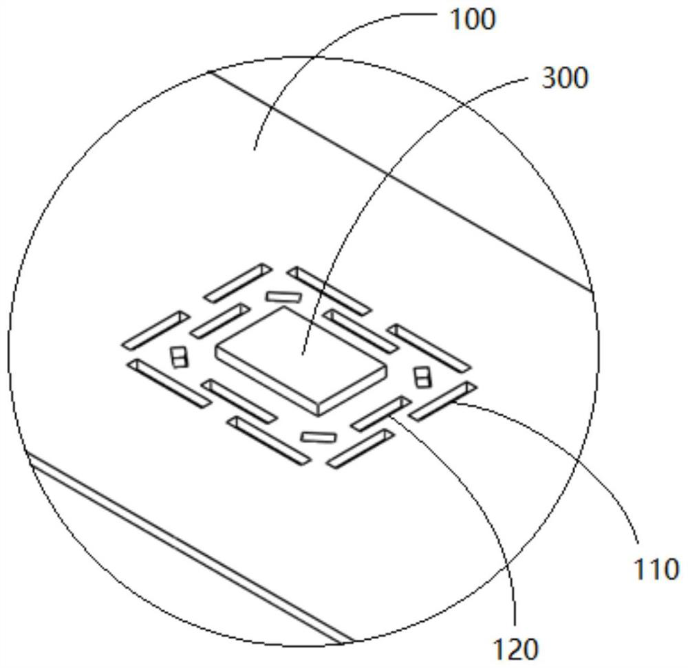
The invention discloses a circuit board with a windproof constant temperature device. The circuit board comprises a circuit board body and the windproof constant temperature device arranged on the circuit board body, wherein a first through hole group is formed in the circuit board body in the circumferential direction of the thermosensitive device; the windproof constant-temperature device comprises an upper protection assembly and a lower protection assembly; the upper protection assembly comprises a heat storage pipe and a heat insulation cover arranged above the heat storage pipe and the first through hole set in a covering mode. The lower protection assembly comprises a heat insulation plate which is located on the projection, perpendicular to the circuit board body, of the thermosensitive device, and the heat insulation plate covers the first through hole set. Through the first through hole group arranged around the thermosensitive heating device, partial heat is prevented from being transmitted from the circuit board body to the thermosensitive heating device, and the thermosensitive heating device is isolated from the surrounding environment through the windproof constant temperature device, so that the influence of the surrounding heating device on the thermosensitive heating device is reduced.

Description

technical field [0001] The invention relates to the technical field of circuit board protection, in particular to a circuit board with a windproof and constant temperature device. Background technique [0002] Some devices in the electronic system are sensitive to changes in the surrounding wind speed and temperature. In order to avoid being blown by the wind or being affected by the surrounding heating devices, the usual practice is to add a metal cover on the front and back sides of the device to avoid this. The device and the circuit board at the bottom of the device are blown by the wind, and at the same time have a certain insulation effect. [0003] However, on the one hand, this method is greatly affected by other heating devices on the circuit board, that is, the heat emitted by other devices on the circuit board can be conducted to the sensitive device through the circuit board, causing the temperature of the tooth device to change, thereby improving the performance...

Claims


Application Information

Patent Timeline
IPC IPC(8): H05K1/18H05K1/02
CPCH05K1/18H05K1/0201H05K1/0213H05K1/02
Inventor 高学东
Owner CIG SHANGHAI
Learn More