Ventilation system and air conditioner

A fresh air system and air-conditioning technology, applied in ventilation systems, air-conditioning systems, lighting and heating equipment, etc.

Pending Publication Date: 2021-07-30
PANASONIC HOME APPLIANCES AIR CONDITIONING GUANGZHOU CO LTD
View PDF0 Cites 2 Cited by
  • Summary
  • Abstract
  • Description
  • Claims
  • Application Information

AI Technical Summary

Problems solved by technology

[0002] In the existing fresh air system air conditioner, the fresh air component installed on the air conditioner body can only absorb fresh air from the outside to enter the room. To realize the exhaust of indoor dirty air to the outside, it is necessary to add a separate exhaust component, which is combined with the indoor air conditioner to achieve air suction. With the exhaust function, the separate exhaust assembly installed on the outdoor side needs to drill additional holes in the customer's room through the exhaust pipe, resulting in the need to drill 2 through-wall holes

Method used


Image

  • Ventilation system and air conditioner
  • Ventilation system and air conditioner
  • Ventilation system and air conditioner

Examples


Embodiment 1

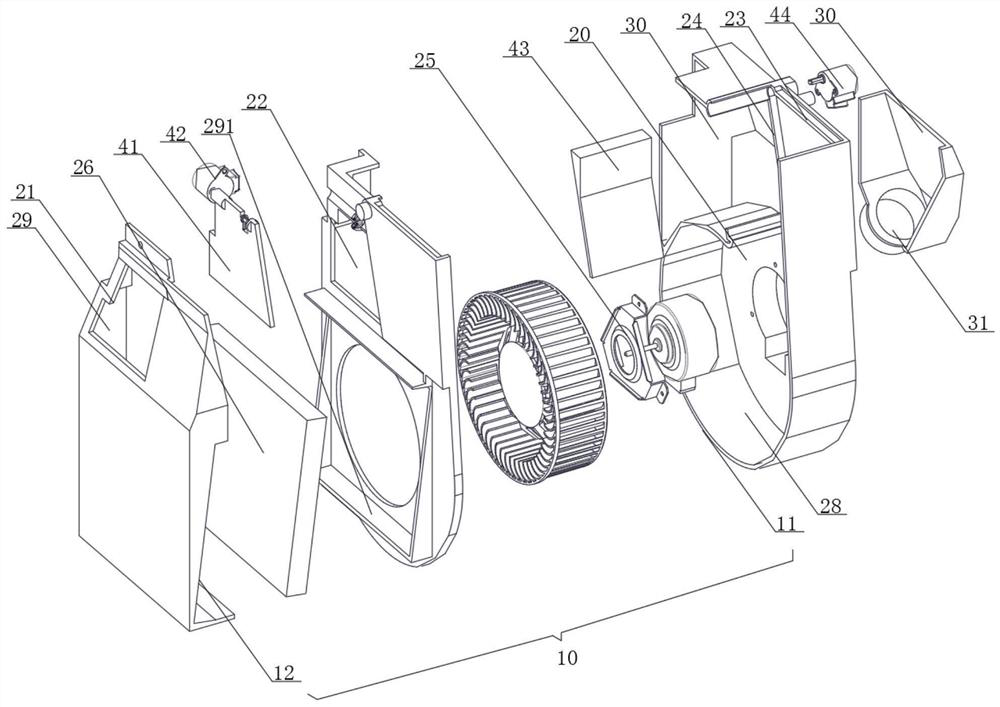
[0045] see figure 1 , which is an exploded view of the fresh air system according to Embodiment 1 of the present invention. The fresh air system includes: a casing 10 , an air chamber 20 disposed in the casing 10 , a switching air duct 30 and a damper mechanism.

[0046]The air chamber 20 is provided with an air inlet 21, a first conversion port 22, an air outlet 23, a second conversion port 24, a fan 25 and a filtering mechanism 26, and the air inlet 21 and the first conversion port 22 pass through The filter mechanism 26 is communicated with the air inlet end of the fan 25, and the air outlet 23 and the second transition port 24 are all communicated with the air inlet end of the fan 25; There is a new air port 31, and the conversion channel communicates with the first conversion port 22 and the second conversion port 24; The two conversion ports 24 are connected to open and close the air inlet 21 , the first conversion port 22 , the air outlet 23 and the second conversion p...

Embodiment 2

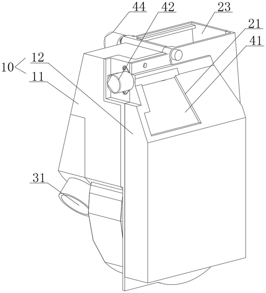
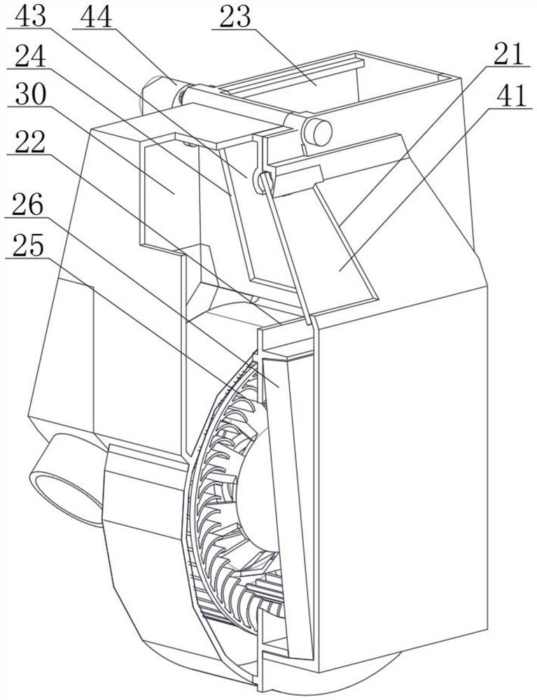
[0058] see Figure 11 , which is an exploded view of the fresh air system in Embodiment 2 of the present invention. The difference between the fresh air system in Embodiment 2 of the present invention and Embodiment 1 is that the air outlet 23 of the fresh air system in this embodiment can be set on the front side of the air conditioner , to avoid the situation that the air outlet 23 is arranged on the top of the air conditioner and is easy to accumulate dust. The air chamber 20 includes a fan chamber 28 and a filter chamber 29 that communicate with each other. The air inlet 21, the first conversion port 22 and the The filter mechanism 26 is arranged in the filter chamber 29 , the air outlet 23 , the second conversion port 24 and the fan 25 are arranged in the fan chamber 28 , and the air outlet 23 is located at one side of the casing 10 .

[0059] Please also see Figure 12 , Figure 13 and Figure 14 , Figure 12 It is a structural schematic diagram of the fresh air syst...

Embodiment 3

[0063] see Figure 21 , which is an exploded diagram of the fresh air system in Embodiment 3 of the present invention. The difference between the fresh air system in Embodiment 3 of the present invention and Embodiment 1 is that the blower fan 25 adopts a double-suction centrifugal fan with two air inlet ends, which improves the ventilation of the fresh air. The air chamber 20 includes a fan chamber 28 and a filter chamber 29 communicating with each other, the air inlet 21, the first conversion port 22 and the filter mechanism 26 are arranged in the filter chamber 29, and the air outlet 23. The second conversion port 24 and the fan 25 are arranged in the fan chamber 28, the fan chamber 28 is connected to the filter chamber 29 through two fan connection ports 292, and the air inlet end of the fan 25 is connected to the fan The ports 292 are connected in one-to-one correspondence. Of course, other suitable air-conditioning structures can also be designed in some other implement...


PUM


Abstract

The invention provides a ventilation system. The ventilation system comprises a shell, an air chamber, a conversion air duct and an air valve mechanism, wherein the air chamber, the conversion air duct and the air valve mechanism are arranged in the shell; an air inlet, a first conversion opening, an air outlet, a second conversion opening, a fan and a filtering mechanism are arranged in the air chamber, the air inlet and the first conversion opening are in communication with the air inlet end of the fan through the filtering mechanism, and the air outlet and the second conversion opening are in communication with the air inlet end of the fan; a ventilation opening is formed in the conversion air duct, and the conversion air duct communicates with the first conversion opening and the second conversion opening; and the air valve assembly is connected with the air inlet, the first conversion opening, the air outlet and the second conversion opening. According to the ventilation system, the double-flow-direction conversion air duct design is adopted to achieve suction and exhaust integration of a ventilator, air duct switching is achieved through the air valve assembly, and the ventilation assembly achieves multiple functions of outdoor fresh air suction, indoor dirty air exhaust and indoor air purification circulation.

Description

technical field [0001] The invention relates to the technical field of air conditioning, in particular to a fresh air system and an air conditioner. Background technique [0002] In the existing fresh air system air conditioner, the fresh air component installed on the air conditioner body can only absorb fresh air from the outside to enter the room. To realize the exhaust of indoor dirty air to the outside, it is necessary to add a separate exhaust component, which is combined with the indoor air conditioner to achieve air suction. With the exhaust function, the separate exhaust assembly installed on the outdoor side requires additional holes to be drilled through the exhaust pipe in the customer's room, resulting in the need to drill 2 through-wall holes. Contents of the invention [0003] The purpose of the present invention is to overcome the shortcomings and deficiencies in the prior art, and provide a fresh air system and an air conditioner. [0004] An embodiment o...

Claims


Application Information

Patent Timeline
IPC IPC(8): F24F7/007F24F7/003F24F1/0035F24F13/02F24F13/28F24F11/89
CPCF24F7/007F24F13/02F24F13/28F24F11/89F24F1/0035
Inventor 杨阳张勇庄华虎陈观炎邓妃恒
Owner PANASONIC HOME APPLIANCES AIR CONDITIONING GUANGZHOU CO LTD
Why Eureka
Try Eureka