Method for fracturing metal component, and method for fracturing connecting rod

A technology of metal parts and parts, applied in the field of fracture of connecting rods, can solve the problem that the fracture surface cannot be obtained, and achieve the effect of suppressing three-dimensional offset and simple cost burden

Active Publication Date: 2021-07-23
YASUNAGA CORP
View PDF7 Cites 0 Cited by
  • Summary
  • Abstract
  • Description
  • Claims
  • Application Information

AI Technical Summary

Problems solved by technology

[0005]However, for the groove formed only in the connecting rod, since there are multiple failure origins in the groove, the cracks develop from multiple directions. Interfering with each other and moving three-dimensionally, sometimes a good fracture surface cannot be obtained

Method used


Image

  • Method for fracturing metal component, and method for fracturing connecting rod
  • Method for fracturing metal component, and method for fracturing connecting rod
  • Method for fracturing metal component, and method for fracturing connecting rod

Examples


Embodiment Construction

[0038] Below, based on Figure 1 to Figure 10 The shown first embodiment describes the present invention.

[0039] figure 1 A front view of a connecting rod 1 (hereinafter referred to as connecting rod 1 ) as a product is shown.

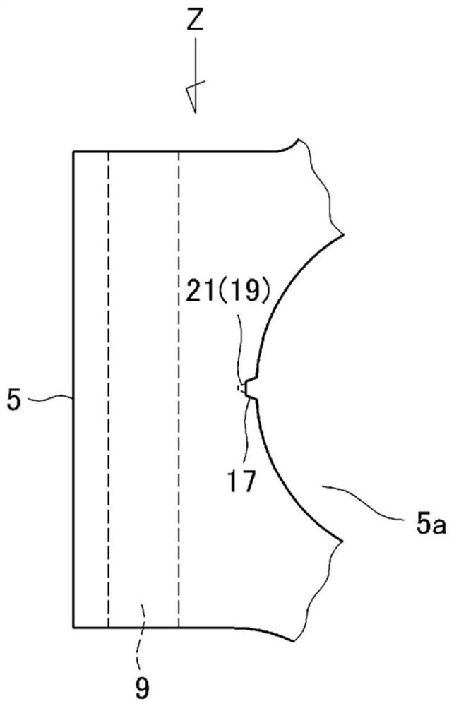
[0040] The connecting rod 1 has: a small end portion 3 having a piston pin hole 3a, a large end portion 5 having a crank pin hole 5a (equivalent to a prescribed through hole in the present application), and the small end portion 3 and the large end portion. Rod 7 to which ends 5 are joined. In addition, a pair of bolt holes 9 (one each on the left and right sides) located on the side of the crank pin hole 5 a are provided in the large end portion 5 . In addition, the bolt hole 9 is formed by a hole extending in a direction perpendicular to the crank pin hole 5a.

[0041] The large end portion 5 is divided into a main body portion 15a and a semicircular arc-shaped cover portion 15b so that a crank pin (not shown) can be sandwiched therein. The co...


PUM


Abstract

The present invention relates to a method for fracturing a metal component 1, B which has a prescribed through hole 5a, and which has a groove portion 17 formed continuously from a first open end of the through hole to a second open end thereof, at a position corresponding to an inner circumferential surface of the through hole. The method enables the metal component to fracture from the groove portion, and includes identifying a position delta, delta1, delta2 in the groove portion of the metal component at which stress is to be caused to concentrate when the metal component starts to fracture; forming a stress concentration portion 19 in a position in a bottom portion of the groove portion corresponding the identified position in the groove portion, in order to set the identified position as a failure starting point; and causing a crack S1 to be generated from the stress concentration portion 19 on the groove portion earlier than at each portion of the groove portion when the metal component begins to fracture, thereby causing a crack S2 to develop from each portion of the groove portion.

Description

technical field [0001] The present invention relates to a method of fracturing a metal part broken from a through hole and a method of fracturing a connecting rod. Background technique [0002] Metal parts having through-holes may be used as a pair of products by combining parts broken and divided from the through-holes. A connecting rod (hereinafter referred to as a connecting rod) is known as a typical metal part. [0003] In the connecting rod, a load is applied to the through hole of the large end in the direction of expansion, the large end is broken and divided into a main body and a cover, and the unevenness generated on the broken fracture surface is used for positioning, thereby When fastening the main body portion and the cover portion with bolts, positioning can be performed with high precision even in a state in which positioning pins are omitted. [0004] The connecting rod is often configured such that grooves are formed continuously from the opening end on o...

Claims


Application Information

Patent Timeline
Patent Type & Authority Applications(China)
IPC IPC(8): B26F3/02F16C7/00
CPCB26F3/02F16C9/045F16C7/023F16C7/08B23D15/04F16C7/02B23D15/12B23P13/00
Inventor 长谷浩一贝增祐士
Owner YASUNAGA CORP
Why Eureka
Try Eureka