
Dual-power vertical take-off and landing fixed-wing unmanned aerial vehicle

A vertical take-off and landing, fixed-wing technology, applied in the field of unmanned aerial vehicles, can solve the problems of increasing the overall weight and flight resistance of the equipment, increasing the operating load of the engine, and increasing the incidence of failures, achieving good protection effects and preventing fuselage collisions Impaired, reduced effect of requirement restrictions

Pending Publication Date: 2021-07-23
宁波阿瑞斯自动化技术有限公司
View PDF5 Cites 0 Cited by
  • Summary
  • Abstract
  • Description
  • Claims
  • Application Information

AI Technical Summary

Problems solved by technology

At the same time, it will increase the overall weight and flight resistance of the equipment, increase the operating load of the engine, increase the failure rate, and weaken the endurance. Therefore, we propose a dual-power vertical take-off and landing fixed-wing UAV

Method used


Image

  • Dual-power vertical take-off and landing fixed-wing unmanned aerial vehicle
  • Dual-power vertical take-off and landing fixed-wing unmanned aerial vehicle
  • Dual-power vertical take-off and landing fixed-wing unmanned aerial vehicle

Examples


Embodiment 1

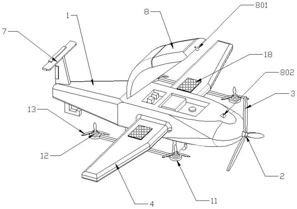
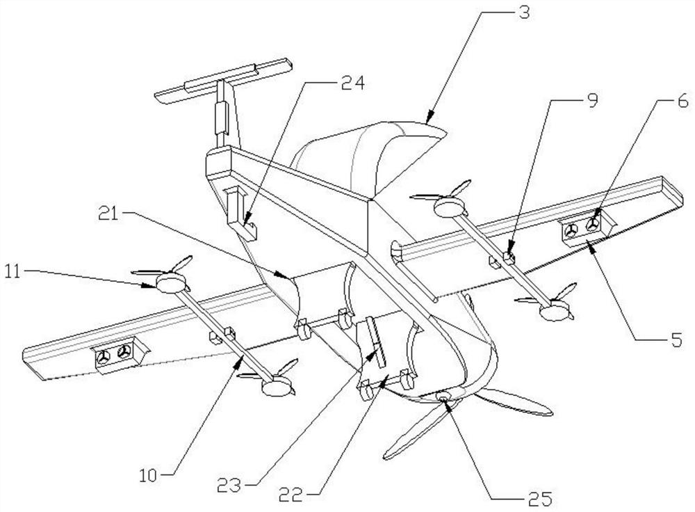
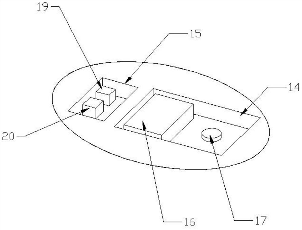
[0026] see Figure 1-5 As shown, the present embodiment is a dual-power vertical take-off and landing fixed-wing unmanned aerial vehicle, comprising a fuselage 1, a propeller engine 2 is installed on the right end of the fuselage 1, and the output end of the propeller engine 2 is connected with a propeller blade 3, and the fuselage The front and rear sides of 1 are equipped with fixed wing 4, the bottom of fixed wing 4 is connected with power frame 5, the left end of power frame 5 is installed with worm gear thrust engine 6, the top left side of fuselage 1 is connected with empennage assembly 7, fuselage 1 The upper end of the cover body 8 is hinged.

[0027] Mounting bases 9 are connected to the inner sides of the bottoms of the two fixed wings 4, and the two mounting bases 9 are arranged symmetrically with respect to the fuselage 1. Supporting arms 10 are connected to the mounting bases 9, and motor bases 11 are connected to the left and right ends of the supporting arms 10....

Embodiment 2

[0031] see Figure 1-5 As shown, the present embodiment is a dual-power vertical take-off and landing fixed-wing unmanned aerial vehicle, comprising a fuselage 1, a propeller engine 2 is installed on the right end of the fuselage 1, and the output end of the propeller engine 2 is connected with a propeller blade 3, and the fuselage The front and rear sides of 1 are equipped with fixed wing 4, the bottom of fixed wing 4 is connected with power frame 5, the left end of power frame 5 is installed with worm gear thrust engine 6, the top left side of fuselage 1 is connected with empennage assembly 7, fuselage 1 The upper end of the cover body 8 is hinged.

[0032] Mounting bases 9 are connected to the inner sides of the bottoms of the two fixed wings 4, and the two mounting bases 9 are arranged symmetrically with respect to the fuselage 1. Supporting arms 10 are connected to the mounting bases 9, and motor bases 11 are connected to the left and right ends of the supporting arms 10....


PUM


Abstract

The invention discloses a dual-power vertical take-off and landing fixed-wing unmanned aerial vehicle. The unmanned aerial vehicle comprises a fuselage, a propeller engine is installed at the right end of the fuselage, propeller blades are connected to the output end of the propeller engine, fixed wings are installed on the front side and the rear side of the fuselage, and a power frame is connected to the bottoms of the fixed wings. A worm wheel thrust engine is installed at the left end of the power frame, an empennage assembly is connected to the left side of the top of the fuselage, and a cover body is hinged to the upper end of the fuselage. The structural design is reasonable, the requirement limitation on the take-off and landing environment is greatly reduced, dual-power driving can be realized in the flight process, the overlarge load of a single engine is avoided, the fault occurrence probability is reduced, the cruising ability of the equipment is enhanced, the functions are diversified, and the application is more diversified.

Description

technical field [0001] The invention relates to the technical field of unmanned aerial vehicles, in particular to a dual-power vertical take-off and landing fixed-wing unmanned aerial vehicle. Background technique [0002] Unmanned aircraft, referred to as "UAV", is an unmanned aircraft that is controlled by radio remote control equipment and its own program control device, or is completely or intermittently operated autonomously by an on-board computer. Drones are often better suited for missions that are too "dumb, dirty or dangerous" than manned aircraft. According to the application field, UAV can be divided into military and civilian. Civilian use is the real rigid demand of drones; currently it is used in aerial photography, agriculture, plant protection, micro selfie, express delivery, disaster relief, observation of wild animals, monitoring of infectious diseases, surveying and mapping, news reports, power inspections, disaster relief, film and television shooting, ...

Claims


Application Information

Patent Timeline
IPC IPC(8): B64D27/02B64D47/08B64D47/00B64C27/14B64C27/22B64C5/00H02J7/35
CPCB64D27/02B64D47/08B64D47/00B64C27/14B64C27/22B64C5/00H02J7/35B64D27/026
Inventor 张磊
Owner 宁波阿瑞斯自动化技术有限公司
Learn More