
Preparation method of solid rocket engine composite material shell

A technology of composite materials and solid rockets, which is applied in the direction of rocket engine devices, machines/engines, mechanical equipment, etc., can solve the problem of reducing the bonding quality of the first interface between the thermal insulation head and the thermal insulation layer of the column section, the quality of the inner surface of the shell, The heat insulation head affects the strength of the solid rocket motor composite shell and other issues, and achieves the effect of avoiding the problem of wire winding around the mandrel

Active Publication Date: 2021-07-23
THE GENERAL DESIGNING INST OF HUBEI SPACE TECH ACAD
View PDF7 Cites 0 Cited by
  • Summary
  • Abstract
  • Description
  • Claims
  • Application Information

AI Technical Summary

Problems solved by technology

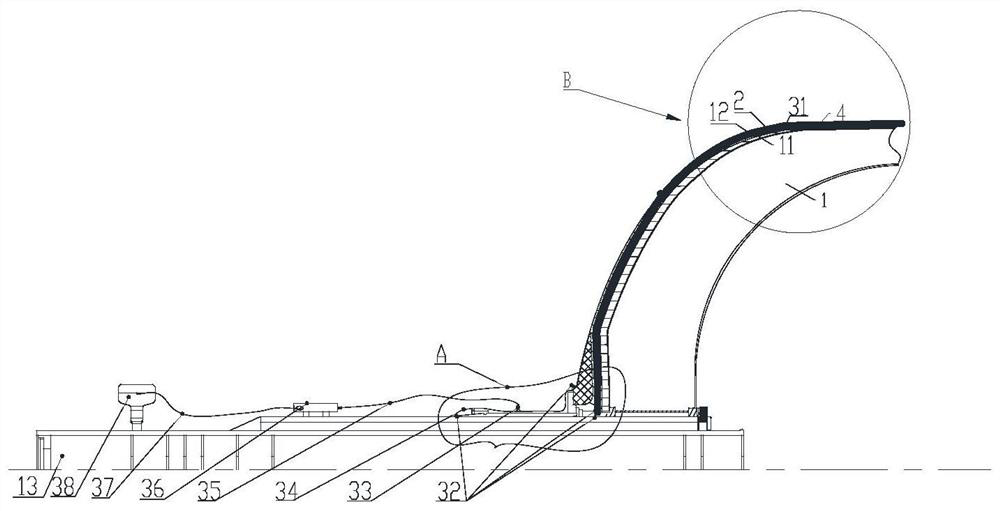
[0005] In order to solve the difficulty in bonding the heat-insulating head to the mandrel after assembly in the prior art and affect the strength of the solid rocket motor composite shell, reduce the bonding between the heat-insulating head and the thermal insulation layer of the column section, the bonding quality of the first interface and the inside of the shell. To solve the problem of surface quality, the embodiment of the present invention provides a method for preparing a solid rocket motor composite shell

Method used


Image

  • Preparation method of solid rocket engine composite material shell
  • Preparation method of solid rocket engine composite material shell
  • Preparation method of solid rocket engine composite material shell

Examples


Embodiment Construction

[0029] In order to make the purpose, technical solutions and advantages of the embodiments of the present invention clearer, the technical solutions in the embodiments of the present invention will be clearly and completely described below in conjunction with the drawings in the embodiments of the present invention. Obviously, the described embodiments It is a part of embodiments of the present invention, but not all embodiments. Based on the embodiments of the present invention, all other embodiments obtained by persons of ordinary skill in the art without making creative efforts belong to the protection scope of the present invention.

[0030] In the description of the present invention, it should be noted that the orientation or positional relationship indicated by the terms "upper", "lower", etc. is based on the orientation or positional relationship shown in the drawings, and is only for the convenience of describing the present invention and simplifying the description. ...


PUM


Abstract

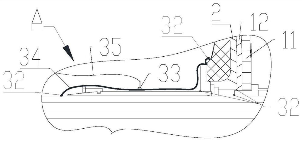
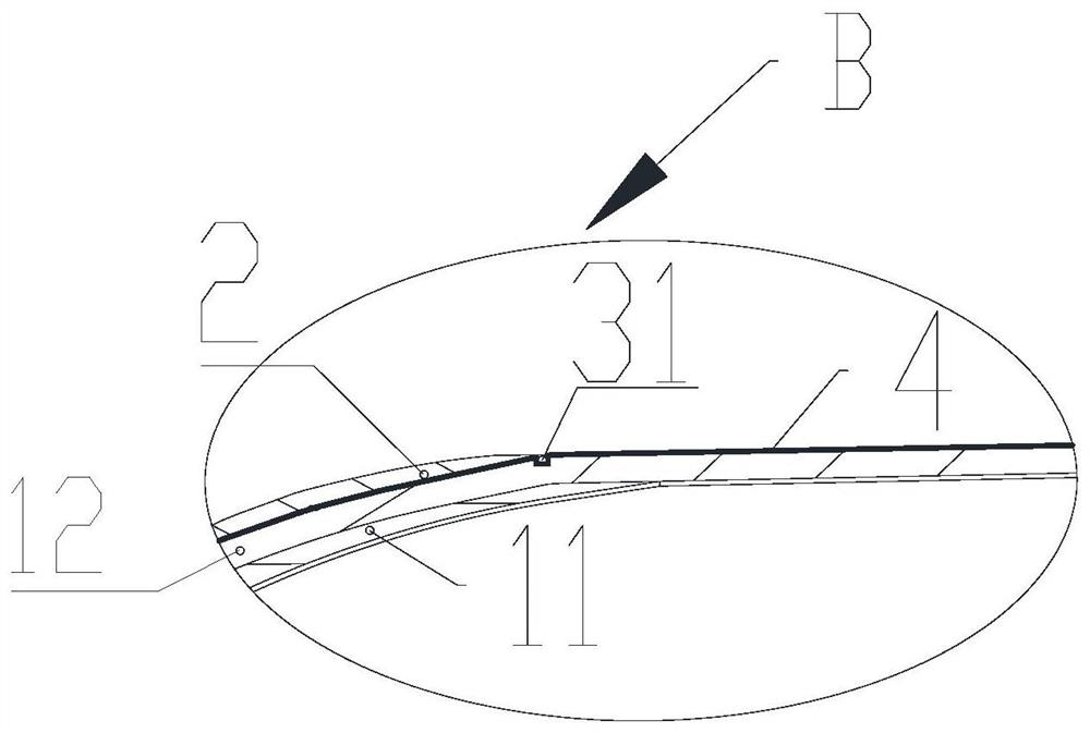
The invention relates to a preparation method of a solid rocket engine composite material shell. The preparation method comprises the following steps that an airtight demolding layer is manufactured on the outer surface of a core mold; a heat-insulating end socket and a sealing piece are assembled, so that the heat-insulating end socket and the demolding layer become one part of a vacuumizing system; vacuumizing is carried out to enable the heat-insulating end socket to be tightly attached to the demolding layer; and a spiral fiber layer is integrally wound on the outer surface of the core mold. The sealing performance of the heat-insulating end socket and the demolding layer is utilized, the heat-insulating end socket and the demolding layer become a part of the vacuumizing system by installing a sealing strip and a vacuum bag, vacuumizing is carried out before winding of the spiral fiber layer, the heat-insulating end socket is attached to the demolding layer, then the heat-insulating end socket is attached to the core mold, vacuumizing is stopped after winding of 1-2 complete cycles, at the moment, the heat-insulating end socket cannot rebound due to the constraint of the spiral fiber layer, so that the problem that the quality of the solid rocket engine composite material shell is affected due to the fact that the heat-insulating end socket and the end socket section core mold are not attached is solved.

Description

technical field [0001] The invention relates to the field of solid rocket motor composite material shells, in particular to a preparation method for solid rocket motor composite material shells. Background technique [0002] The solid rocket motor composite shell includes front and rear joints, front and rear skirts, fiber winding layers and heat insulation layers. In the prior art, the heat insulation layers of the front and rear heads are generally molded together with the front and rear joints to form an integral heat insulation head. The shell molding process is mainly as follows: first prepare the mandrel, then install the front and rear heat insulating heads on the mandrel respectively, then attach the column section heat insulation layer, and then wind the whole body on the surface of the column section heat insulation layer and the front and rear heat insulation heads Helical fiber layers, and finally the upper skirt, curing and demoulding. [0003] The front and re...

Claims


Application Information

Patent Timeline
IPC IPC(8): B29C70/34B29C70/32B29C70/54F02K9/34
CPCB29C70/342B29C70/32B29C70/54F02K9/34
Inventor 赵飞周睿司学龙万佩钟志文武丹
Owner THE GENERAL DESIGNING INST OF HUBEI SPACE TECH ACAD
Learn More