Eureka AIR delivers breakthrough ideas for toughest innovation challenges, trusted by R&D personnel around the world.

Automatic fixing and clamping tooling for production and processing of low-voltage power distribution cabinet

A technology for fixing clamping and power distribution cabinets, which is applied in the direction of metal processing equipment, auxiliary devices, manufacturing tools, etc., can solve the problem that the processing of power distribution cabinets is prone to loosening, the effective fixing of power distribution cabinets cannot be guaranteed, and the fixing effect of clamping fixtures is not good. Good and other problems, to achieve the effect of not easy to loose, easy to process, and flexible to use

Pending Publication Date: 2021-07-23
青岛大志美德电气有限公司
View PDF7 Cites 2 Cited by
  • Summary
  • Abstract
  • Description
  • Claims
  • Application Information

AI Technical Summary

Problems solved by technology

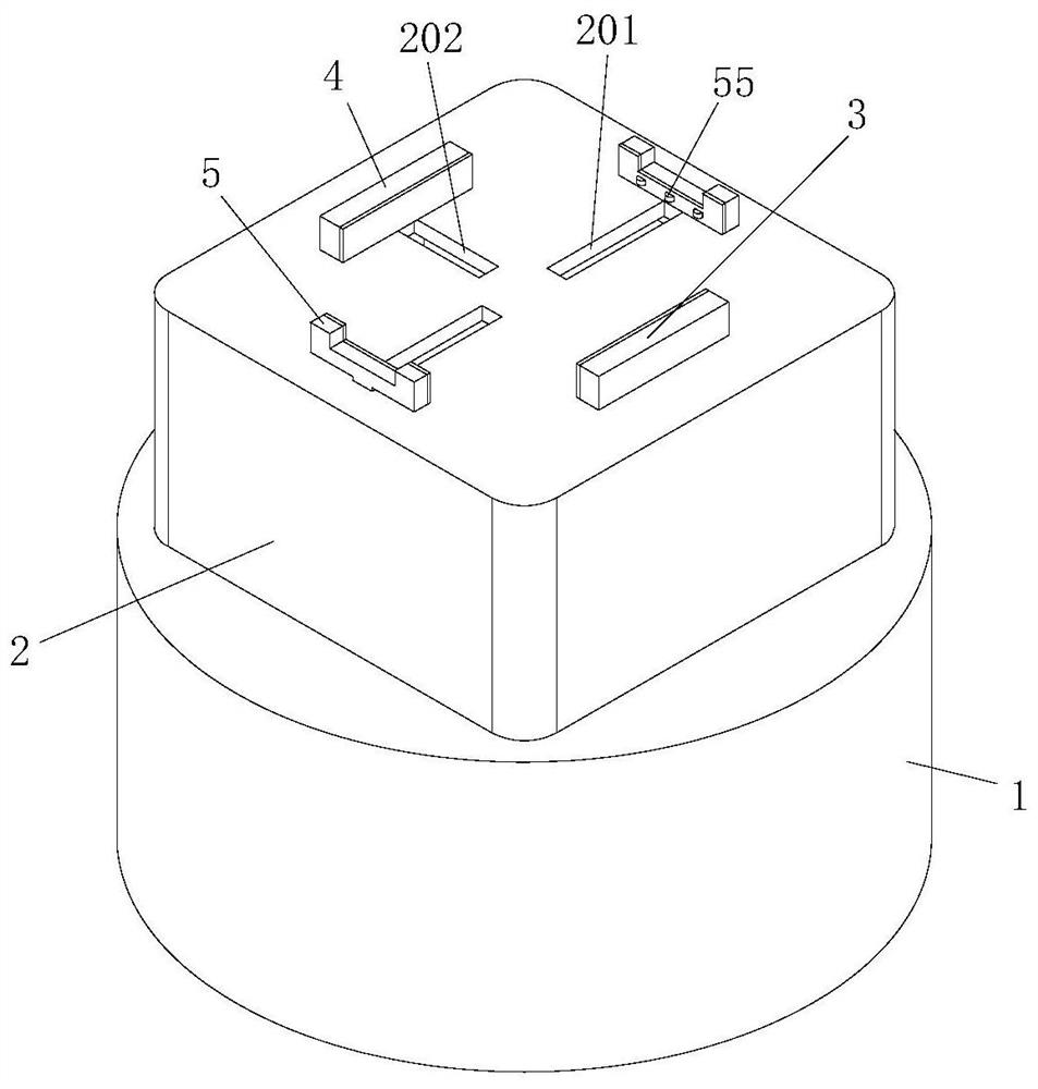
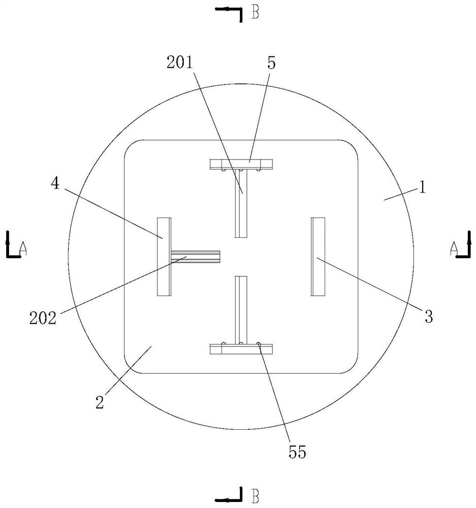
[0005] The purpose of the present invention is to provide an automatic fixing and clamping tool for the production and processing of low-voltage power distribution cabinets. Looseness is prone to occur during the processing of electric cabinets

Method used


Image

  • Automatic fixing and clamping tooling for production and processing of low-voltage power distribution cabinet
  • Automatic fixing and clamping tooling for production and processing of low-voltage power distribution cabinet
  • Automatic fixing and clamping tooling for production and processing of low-voltage power distribution cabinet

Examples


Embodiment Construction

[0025] The following will clearly and completely describe the technical solutions in the embodiments of the present invention with reference to the accompanying drawings in the embodiments of the present invention. Obviously, the described embodiments are only some, not all, embodiments of the present invention. Based on the embodiments of the present invention, all other embodiments obtained by persons of ordinary skill in the art without creative efforts fall within the protection scope of the present invention.

[0026] In the description of the present invention, it should be understood that the terms "upper", "middle", "outer", "inner" and the like indicate orientation or positional relationship, and are only for the convenience of describing the present invention and simplifying the description, rather than indicating or It should not be construed as limiting the invention by implying that a referenced component or element must have a particular orientation, be constructe...


PUM


Abstract

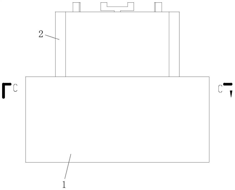
The invention discloses an automatic fixing and clamping tooling for production and processing of a low-voltage power distribution cabinet, and relates to the field of production and processing of power distribution cabinets. The automatic fixing and clamping tooling comprises a base and a movable platform; the movable platform is rotatably connected to the top of the base; a fixed abutting plate is fixedly installed on one side of the top face of the movable platform; a first strip-shaped hole and two second strip-shaped holes are arranged on the top face of the movable platform; a movable side plate is slidably connected into the first strip-shaped hole; the side face, close to the center of the movable platform, of the movable side plate is rotatably connected with a plurality of rollers; movable push plates are slidably connected into the second strip-shaped holes; and second air cylinders are fixedly installed on the inner bottom wall of the base, and movable columns are rotatably connected to the tops of the second air cylinders. The fixed abutting plate, the movable push plates and the two movable side plates are attached to the four faces of the power distribution cabinet, the stability and firmness of the power distribution cabinet are guaranteed while operation is easy, the movable platform can rotate through cooperation of a rack and a gear ring, the rotating angle of the power distribution cabinet at the top of the movable platform can be adjusted conveniently, and the power distribution cabinet can be machined conveniently.

Description

technical field [0001] The invention belongs to the technical field of production and processing of power distribution cabinets, in particular to an automatic fixing and clamping tool for production and processing of low-voltage power distribution cabinets. Background technique [0002] Power distribution cabinets are divided into power distribution cabinets, lighting distribution cabinets, and metering cabinets, and are the final equipment of the power distribution system. The power distribution cabinet is the general name of the motor control center. The power distribution cabinet is used in the occasions where the load is relatively scattered and there are few circuits. The motor control center is used in the occasions where the load is concentrated and there are many circuits. The electrical energy distributed to the nearest load, this level of equipment should provide protection, monitoring and control of the load. [0003] During the production and processing of power...

Claims


Application Information

Patent Timeline
IPC IPC(8): B23K37/04
CPCB23K37/0443
Inventor 宫金花李雪史卫臣井长波宫庆智
Owner 青岛大志美德电气有限公司
Why Eureka
Eureka Blog
Learn More