
Soil and water Conservation method of shoulder and band drainage device used for the method

A drainage and strip technology, which is applied in the field of strip drainage, can solve the problems of uncertainty, difficulty in high-speed and long-size continuous production, and impact on construction operations.

Inactive Publication Date: 2003-12-17
胡鸣群 +1
View PDF0 Cites 0 Cited by
  • Summary
  • Abstract
  • Description
  • Claims
  • Application Information

AI Technical Summary

Problems solved by technology

After trial-manufacturing and testing of this kind of drainage fittings, the following problems were found, which need to be improved: (1) Because the drainage fittings are in the shape of thin strips, the area occupied by the hollow part of the cross-section is quite large, often exceeding the solid part. The tensile strength is small, but it is broken or the groove is deformed, which is difficult for high-speed and long-dimension continuous production; in use, the tensile structure of the entire belt body is weak and easy to be pulled apart
(2) When the drainage parts need to be connected horizontally, it is quite difficult. It is inconvenient and inaccurate to use the connecting parts, which will affect the construction work; at the same time, when buried in the soil, the frictional grip of the soil is small, and relative sliding is easy to occur

Method used


Image

  • Soil and water Conservation method of shoulder and band drainage device used for the method
  • Soil and water Conservation method of shoulder and band drainage device used for the method
  • Soil and water Conservation method of shoulder and band drainage device used for the method

Examples


Embodiment Construction

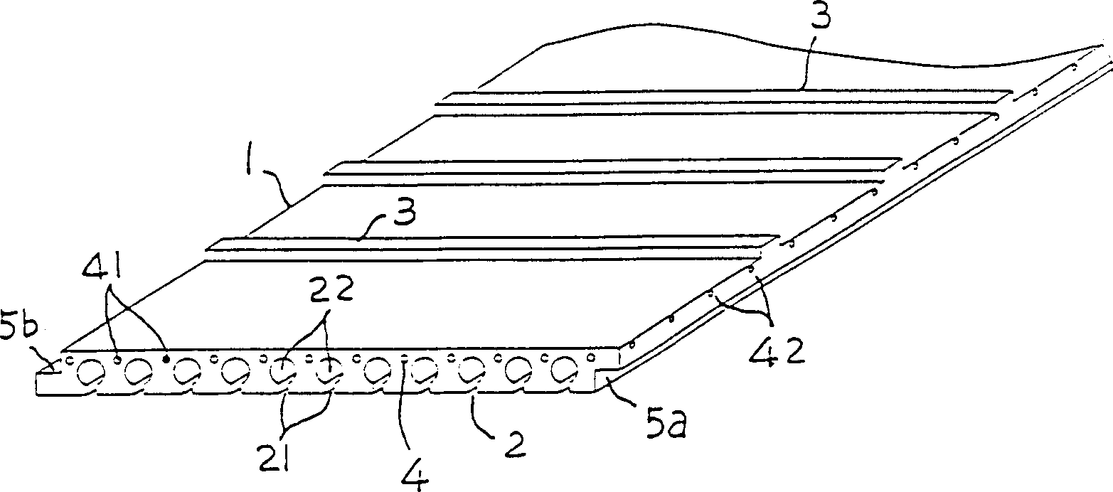
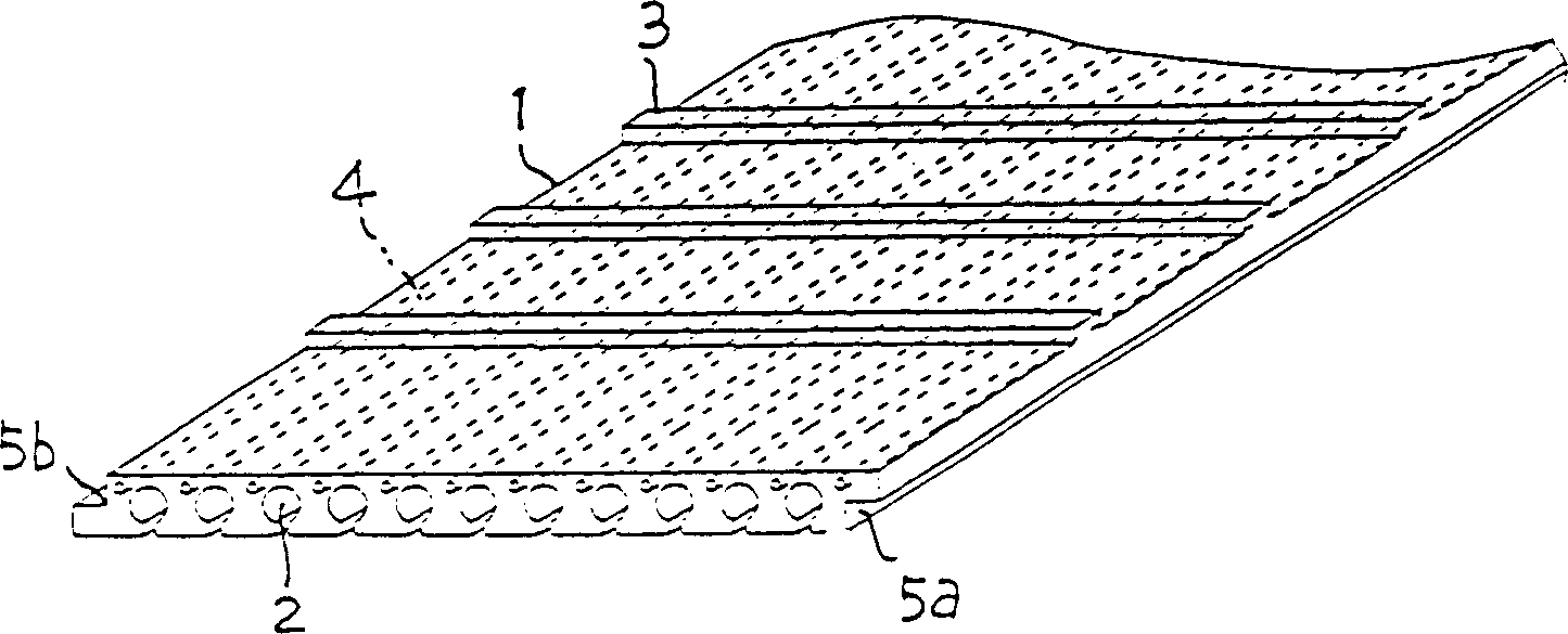
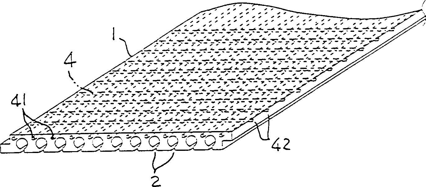
[0015] figure 1 The symbol 1 in the middle is a flat strip-shaped drainage piece, which is usually a flexible strip formed by weather-resistant, acid-resistant and alkali-resistant synthetic resin, but it can also be formed into a plate by semi-rigid or hard synthetic resin according to the needs of the application. shape. Its one side is densely formed with multiple drainage grooves 2 arranged at intervals in the transverse direction and extending from one end to the other in parallel in the longitudinal direction. The mouth 21 of the groove 2 forms a narrow slit that can produce capillary action. Road 22 then expands to be a circular hole section, which is the same as the parent case. The other side of the drainage member 1 is integrally formed with a plurality of transverse ribs 3 arranged at intervals in the longitudinal direction and protruding upwards, so as to increase the frictional grip on the soil when the drainage member 1 is buried in the soil, and avoid the soil ...


PUM


Abstract

The drainage band has in the surface several parallel lengthwise capillary channel mouths and circular drainage channels, and water is sucked from the mouths to the channels by means of capilarity and is drained by means of the water level difference in the channels. In the part of the drainage band without drainage channel, metal wires, synthetic wires or reinforcing parts are embedded longitudinally. The drainage band has on its two sides lapping parts for connecting with the adjacent bands.

Description

technical field [0001] The present invention is an additional invention of No. 86101268 "drainage method and belt-shaped drainage member used in the method" of the previously approved patent application, especially a kind of device that provides the same purpose as the previous case and is more resistant to tension and workability Ribbon drain. Background technique [0002] In the parent case No. 86101268, the inventor once disclosed a drainage method and a strip drainage member suitable for water and soil conservation on hillsides, underground drainage of orchard farmland, drainage systems such as tunnels, roadbeds, and building basements. The effect is to absorb the water in the soil from the mouth of the drainage ditch of the drainage device, and use the drop at both ends of the enlarged ditch and the local siphon force to promote water absorption and collect it for discharge. After trial-manufacturing and testing of this kind of drainage fittings, the following problems...

Claims


Application Information

Patent Timeline
Patent Type & Authority Patents(China)
IPC IPC(8): E02B11/00E02D3/10
Inventor 胡鸣群
Owner 胡鸣群
Learn More