Positioning and fastening type rudder bearing

A fastening type, rudder bearing technology, applied in the direction of steering with rudder, can solve the problems of inconvenient installation and disassembly, cumbersome replacement and maintenance, etc., and achieve the effect of stable pressing and clamping.

Inactive Publication Date: 2021-07-20
DONGTAI YOUMING MARINE FITTINGS
View PDF0 Cites 3 Cited by
  • Summary
  • Abstract
  • Description
  • Claims
  • Application Information

AI Technical Summary

Problems solved by technology

[0002] The rudder bearing is an important device in the rudder system of a ship. The rudder bearing bears the axial and radial loads from the rudder stock and rudder blades to ensure that the rudder blades rotate left and right with the rudder stock, thereby changing the course of the ship or keeping the ship sailing in a straight line; The rod refers to the shaft on which the rudder blade rotates, which is used to bear and transmit the force acting on the rudder blade and the force given to the rudder device by the rudder, that is to say, the steering gear rotates the rudder blade through the rudder stock, and the rudder blade bears the force of water on the rudder blade. The reaction force makes the ship turn; the existing rudder bearing is sleeved on the outside of the rudder stock, and the rudder bearing is used to limit the support of the rudder stock; the installation and disassembly of the existing rudder stock and the rudder stock are inconvenient, and replacement Maintenance is cumbersome, and the stability of the structure needs to be ensured

Method used


Image

  • Positioning and fastening type rudder bearing
  • Positioning and fastening type rudder bearing
  • Positioning and fastening type rudder bearing

Examples


Embodiment Construction

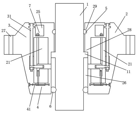
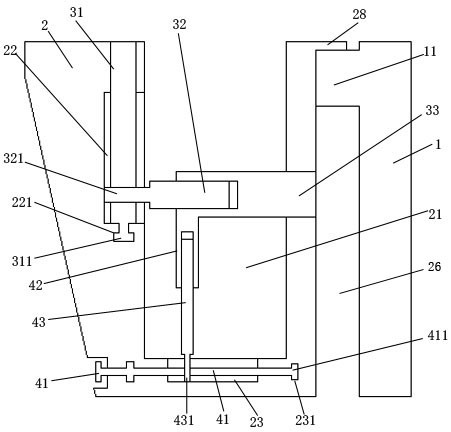
[0019] The content of the present invention will be further described in detail below in conjunction with the accompanying drawings.

[0020] Such as Figures 1 to 3 As shown, a positioning and fastening type rudder bearing includes a rudder bearing body 2, a rudder stock 1, a lateral driving mechanism 4, an axial driving mechanism 3, and a fastening mechanism 7; Channel 26; the upper part of the piercing channel 26 is provided with an abutment ring protrusion 28; the outer side of the middle of the rudder stock 1 is provided with an abutment ring 11; the rudder stock 1 is connected to the rudder bearing from bottom to top In the piercing channel 26 in the middle of the body 2, the abutment ring body 11 on the outside of the middle of the rudder stock 1 abuts on the abutment ring protrusion 28 from bottom to top; The surrounding interior of the connecting channel 26; the two sides of the connecting channel 26 of the rudder bearing body 2 are respectively connected with positi...


PUM


Abstract

The invention discloses a positioning and fastening type rudder bearing which comprises a rudder bearing body, a rudderstock, a transverse driving mechanism, an axial driving mechanism and a fastening mechanism. A fastening mechanism is additionally arranged, a fastening screw rod is installed at the upper end of a movable clamping plate, the upper end of the fastening screw rod penetrates through a penetrating channel of a penetrating positioning plate and then extends to a fastening groove, and the upper end of the fastening screw rod is rotationally connected with a fastening nut in a threaded mode; in this way, the fastening nut is rotationally connected to the upper side face of the penetrating connection positioning plate in an abutting-against or separating mode, so that the movable clamping plate is fastened and positioned, and the movable clamping plate more stably abuts against and clamps the abutting-against ring bodies on the outer sides of the periphery of the middle of the rudderstock.

Description

technical field [0001] The invention relates to a positioning fastening type rudder bearing. Background technique [0002] The rudder bearing is an important device in the rudder system of a ship. The rudder bearing bears the axial and radial loads from the rudder stock and rudder blades to ensure that the rudder blades rotate left and right with the rudder stock, thereby changing the course of the ship or keeping the ship sailing in a straight line; The rod refers to the shaft on which the rudder blade rotates, which is used to bear and transmit the force acting on the rudder blade and the force given to the rudder device by the rudder, that is to say, the steering gear rotates the rudder blade through the rudder stock, and the rudder blade bears the force of water on the rudder blade. The reaction force makes the ship turn; the existing rudder bearing is sleeved on the outside of the rudder stock, and the rudder bearing is used to limit the support of the rudder stock; the...

Claims


Application Information

Patent Timeline
IPC IPC(8): B63H25/38
CPCB63H25/38
Inventor 周树明
Owner DONGTAI YOUMING MARINE FITTINGS
Why Eureka
Try Eureka