Optical tracking structure for navigating surgical power system

A technology of optical tracking and surgical power, which is applied in the field of medical equipment, can solve the problems of small tracking range, influence of navigation accuracy, and small tracking range of surgical power equipment, and achieve the effect of increasing the tracking range, ensuring navigation accuracy, and stable and effective tracking

Active Publication Date: 2021-07-16
LONGWOOD VALLEY MEDICAL TECH CO LTD +2
View PDF16 Cites 2 Cited by
  • Summary
  • Abstract
  • Description
  • Claims
  • Application Information

AI Technical Summary

Problems solved by technology

Such as the tracking tool disclosed in patent 200720012127.0, the optical tracking tool has only one positioning surface, and the positioning surface is a 180° plane, resulting in a very small tracking range. Simply put, the optical tracking system cannot track smoothly from the side Surgical power instruments, therefore, during the operation, the optical tracking system has a small tracking range for the surgical power instruments, which makes the surgical power instruments unable to be tracked stably and effectively, and the accuracy of navigation is also affected, which is not conducive to the smooth operation of navigation conduct

Method used


Image

  • Optical tracking structure for navigating surgical power system
  • Optical tracking structure for navigating surgical power system
  • Optical tracking structure for navigating surgical power system

Examples


Embodiment Construction

[0031] In order to make the purpose, technical solutions and advantages of the present invention clearer, the technical solutions in the present invention will be clearly and completely described below in conjunction with the accompanying drawings in the present invention. Obviously, the described embodiments are part of the embodiments of the present invention , but not all examples. Based on the embodiments of the present invention, all other embodiments obtained by persons of ordinary skill in the art without creative efforts fall within the protection scope of the present invention.

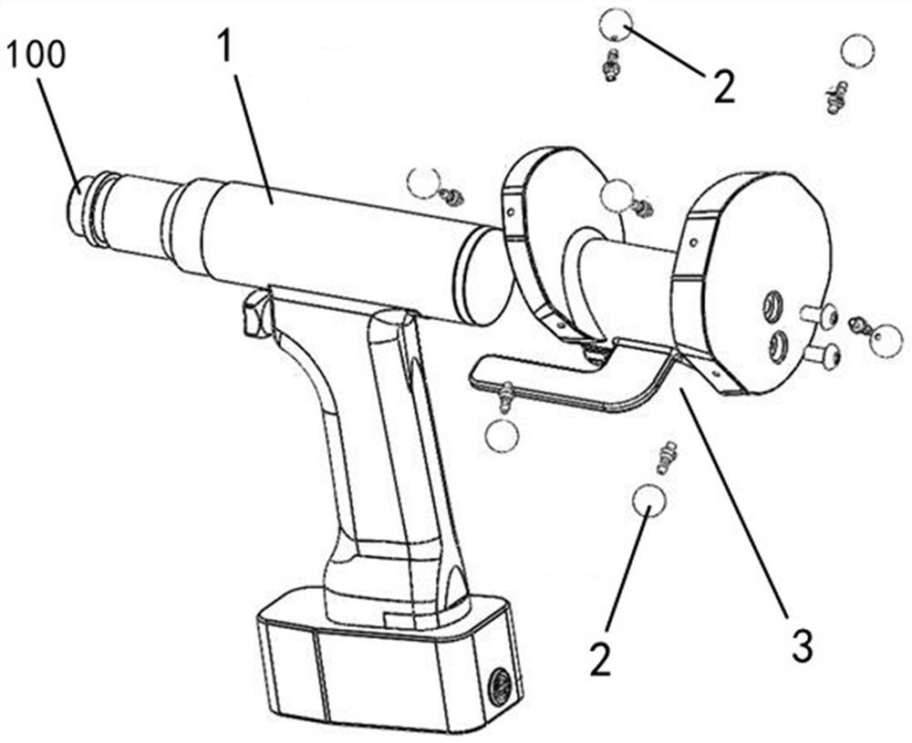
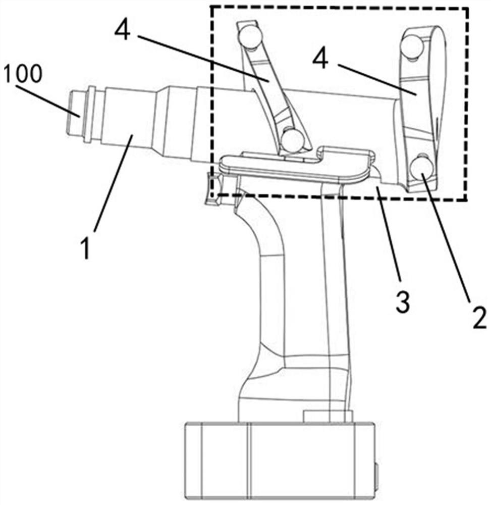
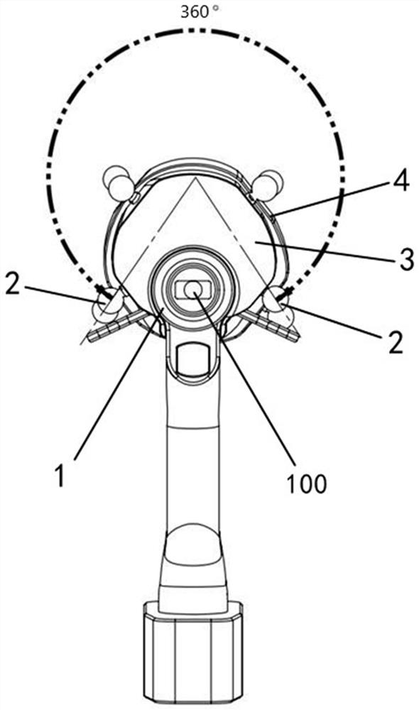
[0032] Combine below Figure 1 ~ Figure 3 An optical tracking structure for navigating the surgical power system of the present invention is shown as shown, including a connector 1, which is used to connect and drive the surgical power instrument (not shown in the figure). When in use, the surgical power instrument is installed At the installation port 100 at the front end of the connector 1...


PUM


Abstract

The invention relates to the technical field of medical instruments, in particular to an optical tracking structure for navigating a surgical power system. The structure comprises a connector for connecting and driving a surgical power instrument, and a navigation support is arranged on the connector. A plurality of reflective balls used for constructing a positioning surface for an optical tracking system are arranged on the navigation support in a following mode, an annular supporting surface is formed on the navigation support, and the plurality of reflective balls are distributed on the surface of the annular supporting surface in a surrounding mode. The optical tracking system performs optical tracking on the spatial position of a surgical power instrument within the angle range of 360 degrees through the plurality of reflective balls. According to the optical tracking structure for navigating the surgical power system, the tracking range of the optical tracking system on the surgical power instrument can be effectively enlarged, the navigation precision in the surgical process is ensured, and surgery navigation is smoother.

Description

technical field [0001] The invention relates to the technical field of medical instruments, in particular to an optical tracking structure for navigating a surgical power system. Background technique [0002] At present, the optical tracking device clinically used for navigation surgery is mainly an optical positioning and tracking system produced by NDI Corporation of Canada. The positioning principle of this type of system is: the infrared light emitted by the binocular position sensor is irradiated on the surgical equipment or instruments equipped with tracking tools, and the small balls (also called reflective balls) on the tracking tools that can reflect infrared light will reflect the infrared light Reflected back to the position sensor and calculated by the built-in software of the system to obtain the position coordinates of the tracking tool (including the position and angle of the tracking tool), so as to realize the positioning and tracking of the corresponding su...

Claims


Application Information

Patent Timeline
IPC IPC(8): A61B34/20
CPCA61B34/20A61B2034/2055
Inventor 张逸凌刘星宇
Owner LONGWOOD VALLEY MEDICAL TECH CO LTD
Why Eureka
Try Eureka