
Mounting mechanism for power detection equipment and use method thereof

A technology for testing equipment and electric power testing, which is applied in the direction of measuring devices, measuring device casings, and parts of electrical measuring instruments. Provide installation efficiency and firm fixation

Inactive Publication Date: 2021-07-13
李思呈
View PDF0 Cites 1 Cited by
  • Summary
  • Abstract
  • Description
  • Claims
  • Application Information

AI Technical Summary

Problems solved by technology

When the existing power detection equipment is fixed, since it is fixed by multiple screws, it is necessary to cycle through the adjustment of multiple screws during the actual installation and disassembly process. In this way, when operating multiple screws, there are Time-consuming and labor-intensive problems. At the same time, the existing power testing equipment needs to calibrate the installation position multiple times when finding the installation position. In this way, a lot of time will be wasted during calibration, thereby reducing the installation efficiency of the equipment.

Method used


Image

  • Mounting mechanism for power detection equipment and use method thereof
  • Mounting mechanism for power detection equipment and use method thereof
  • Mounting mechanism for power detection equipment and use method thereof

Examples


Embodiment Construction

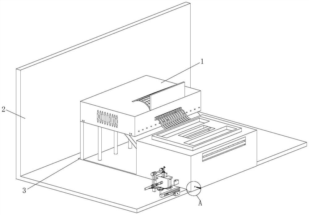
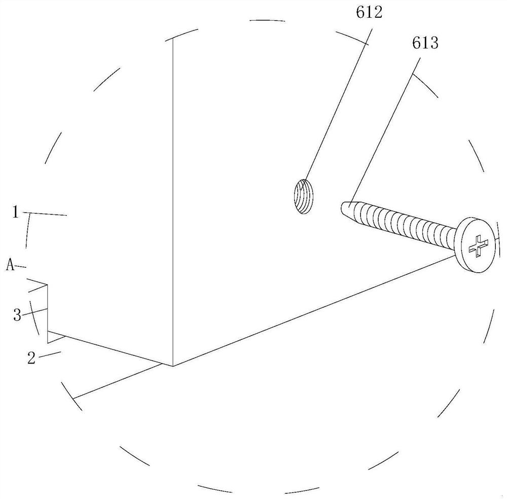
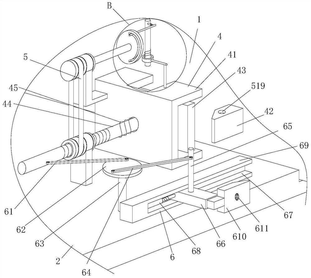
[0037] Attached below Figure 1-5 The present invention is further described with embodiment:

[0038] An installation mechanism for electric power detection equipment and its use method, comprising a detection equipment body 1, a fixed support frame 2 and a positioning chute 3, the positioning chute 3 is set on the fixed support frame 2, and the detection equipment body 1 is movably arranged on the positioning chute In the groove 3, the detection equipment body 1 and the fixed support frame 2 are provided with the same limit mechanism 4, and the setting of the limit mechanism 4 is used to realize the effect of limit locking on the position of the detection equipment body 1, ensuring that the detection equipment body 1 can be stably stored in the positioning chute 3. In the present invention, by modifying the installation structure of the existing detection equipment body 1, the improved installation structure of the detection equipment body 1 can effectively reduce the number...


PUM


Abstract

The invention relates to a mounting mechanism for power detection equipment and a use method thereof. The mounting mechanism comprises a detection equipment body, a fixed support frame and a positioning chute, wherein the positioning chute is formed in the fixed support frame, and the detection equipment body is movably arranged in the positioning chute; The mounting structure of the existing detection equipment body is modified, and the improved mounting structure of the detection equipment body can effectively reduce the number of screws, so that in the mounting process, when the detection equipment body is mounted and disassembled, the effect of efficiently mounting and disassembling the detection equipment body is achieved by reducing the procedure of operating the screws, and meanwhile, according to the improved mounting structure of the detection equipment body, the mounting position of the detection equipment body can be effectively and quickly found, so that the problem that time and labor are consumed when the position of the detection equipment body is calibrated can be avoided, the mounting efficiency of the detection equipment body can be effectively improved, and the mounting structure has a higher application prospect in actual application.

Description

technical field [0001] The invention relates to the technical field of electric power detection equipment, in particular to an installation mechanism for electric power detection equipment and a method for using the same. Background technique [0002] Electric power detection equipment refers to the equipment for test, verification, detection and acceptance of electric power production and grid operation, which provides guarantee for the safety and reliability of electric power operation. When the existing power detection equipment is fixed, since it is fixed by multiple screws, it is necessary to cycle through the adjustment of multiple screws during the actual installation and disassembly process. In this way, when operating multiple screws, there are Time-consuming and labor-intensive problems. At the same time, the existing power testing equipment needs to calibrate the installation position multiple times when finding the installation position. In this way, a lot of tim...

Claims


Application Information

Patent Timeline
Patent Type & Authority Applications(China)
IPC IPC(8): G01R31/00G01R1/04
CPCG01R1/0408G01R31/00
Inventor 李思呈
Owner 李思呈
Learn More