


Quick Research
Generate reliable direction feasibility study reports for your R&D in just a few steps.

Technical Q&A
Discover and master advanced knowledge NOW. Basics, ideas, possibilities, all at once.

Find Solutions
As an expert in R&D theories, this can generate solutions to your technical problems instantly.

Evaluate Feasibility
Analyze your overall solution with one click, know your potential R&D risks in advance.

Monitor Landscape
Get weekly tech updates, stay abreast of the latest tech innovations and key insights.
Automatic discharging system and method for saggars of roller kiln
A technology of automatic unloading and roller kiln, which is applied to the types of furnaces, furnaces, lighting and heating equipment, etc., can solve the problems of inability to realize the limit and inaccurate bead limit, and improve production efficiency and sagger loss rate Low, the effect of reducing impact damage
- Summary
- Abstract
- Description
- Claims
- Application Information
AI Technical Summary
Problems solved by technology
Method used
Image

Examples
Embodiment 1
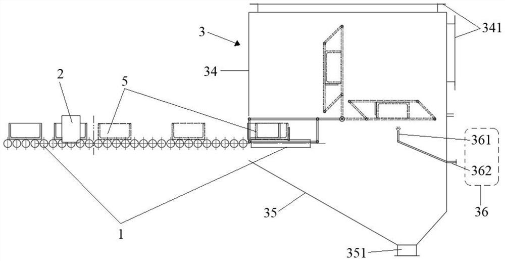
[0119] Such as figure 1 As shown, an automatic unloading system for roller kiln saggers, the system includes: a conveying device 1 , an automatic leveling device 2 and an automatic rotary unloading device 3 . The conveying device 1 includes a first longitudinal conveying roller table 11 , a second longitudinal conveying roller table 12 and a transverse conveying roller table 13 . The second longitudinal conveying roller table 12 is arranged downstream of the first longitudinal conveying roller table 11 , and the front end of the second longitudinal conveying roller table 12 is connected with the end of the first longitudinal conveying roller table 11 . The horizontal conveying roller table 13 is arranged downstream of the second longitudinal conveying roller table 12 , and the end of the second longitudinal conveying roller table 12 is connected to the inner front end of the lateral conveying roller table 13 . The automatic leveling device 2 is arranged on the side of the fi...
Embodiment 2
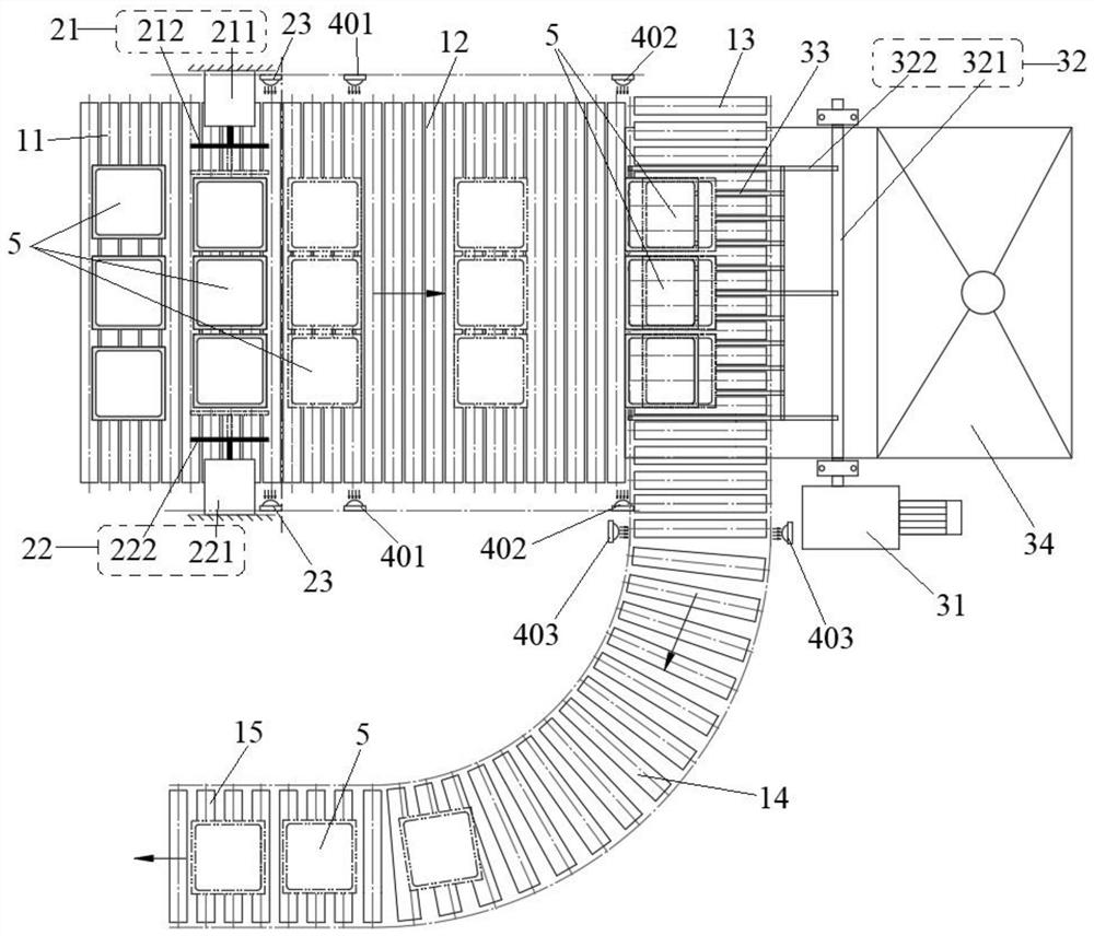
[0121] Repeat Example 1, such as figure 2 As shown, only the automatic leveling device 2 includes a first leveling mechanism 21 , a second leveling mechanism 22 and a leveling photoelectric switch 23 . The first flattening mechanism 21 and the second flattening mechanism 22 are symmetrically arranged on both sides of the first longitudinal conveying roller table 11 . The leveling photoelectric switch 23 is arranged on the side of the first longitudinal conveying roller table 11 and above the first longitudinal conveying roller table 11 .
Embodiment 3
[0123] Repeat Example 2, except that the first flattening mechanism 21 includes a first cylinder 211 and a first push rod 212; the cylinder body of the first cylinder 211 is fixed on the beam on one side of the first longitudinal conveying roller table 11; The piston rod of the first air cylinder 211 is vertically connected with the first push rod 212 ; the axial direction of the first push rod 212 is perpendicular to the roller table axis direction of the first longitudinal conveying roller table 11 .
PUM
 Abstract
Description
Claims
Application Information
 - R&D Engineer
- R&D Manager
- IP Professional
- Industry Leading Data Capabilities
- Powerful AI technology
- Patent DNA Extraction
Browse by: Latest US Patents, China's latest patents, Technical Efficacy Thesaurus, Application Domain, Technology Topic, Popular Technical Reports.
© 2024 PatSnap. All rights reserved.Legal|Privacy policy|Modern Slavery Act Transparency Statement|Sitemap|About US| Contact US: help@patsnap.com