
Sheet feeding apparatus and image forming apparatus

A sheet and feeding technology, applied in the direction of equipment, object supply, transportation and packaging of the electrical recording process using charge graphics, can solve the problems of setting characteristics and other problems

Pending Publication Date: 2021-07-09
CANON KK
View PDF11 Cites 0 Cited by
  • Summary
  • Abstract
  • Description
  • Claims
  • Application Information

AI Technical Summary

Problems solved by technology

Therefore, the sheet inserted into the manual feed tray is set on the tray aligned against the abutment surface, so that there is a disadvantage in the setting characteristics of the sheet

Method used


Image

  • Sheet feeding apparatus and image forming apparatus
  • Sheet feeding apparatus and image forming apparatus
  • Sheet feeding apparatus and image forming apparatus

Examples


no. 1 example

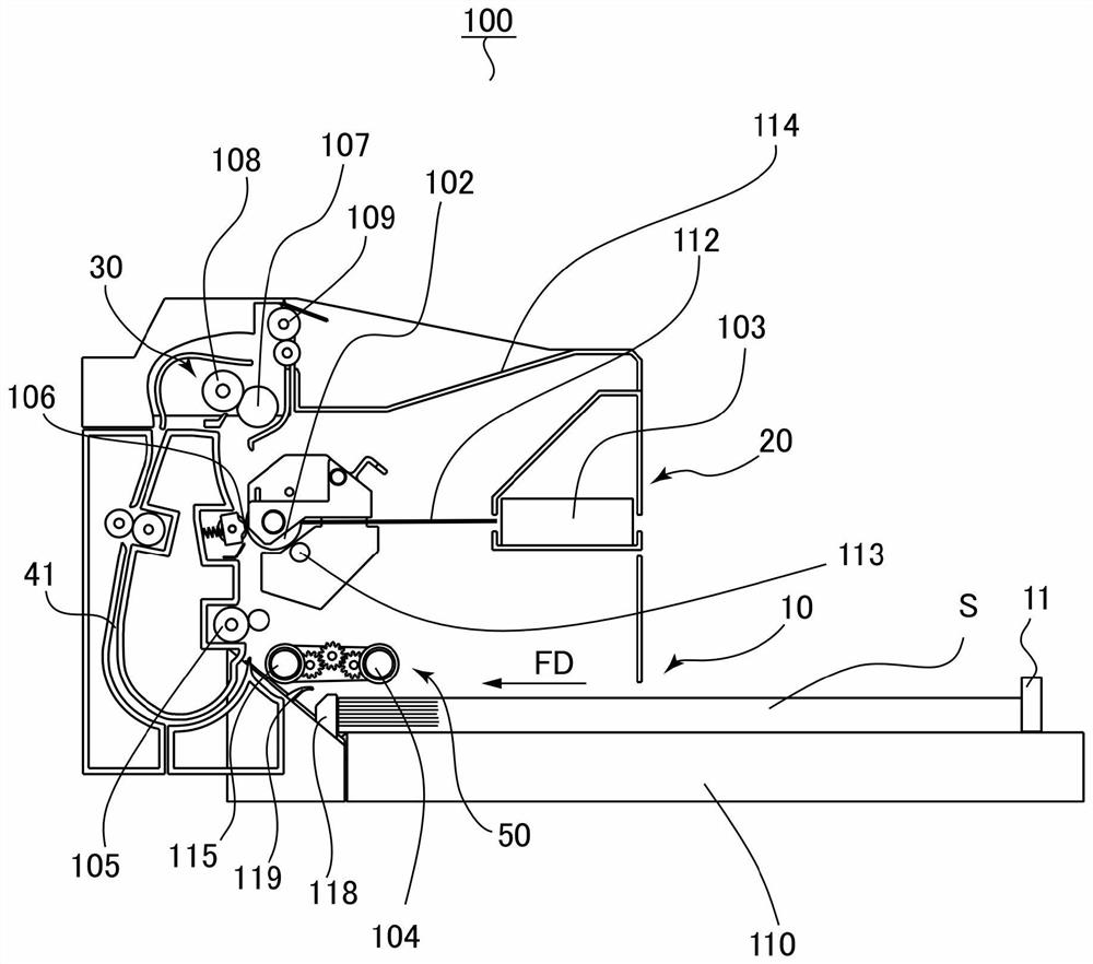
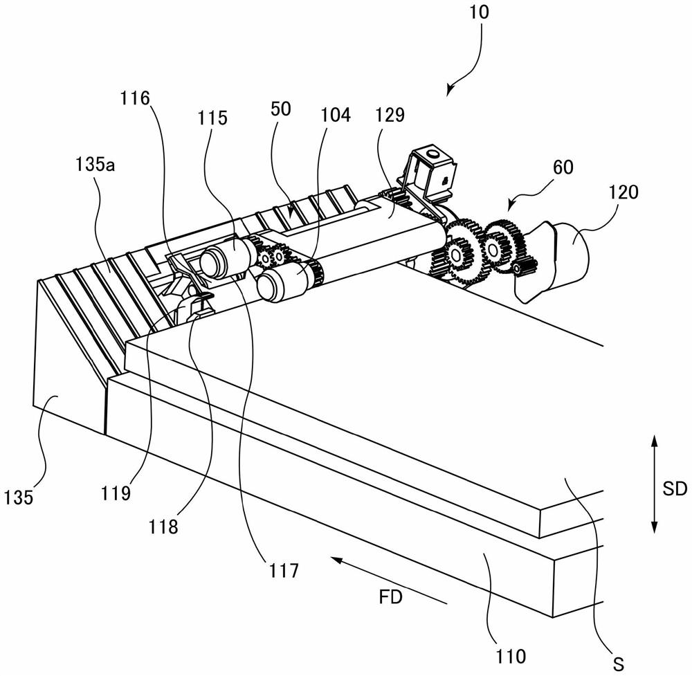
[0032] Now, a first embodiment of the present invention will be described. The printer 100 serving as the image forming apparatus according to the first embodiment is a laser beam printer employing an electrophotographic system. Such as figure 1 As shown, the printer 100 includes: a sheet feeding device 10 provided at a lower portion of the printer 100 , an image forming unit 20 that forms an image on a sheet S fed by the sheet feeding device 10 , a fixing unit 30 , and a sheet Material discharge roller pair 109.

[0033] In a state where an imaging command is output to the printer 100 , imaging processing by the imaging unit 20 starts based on image information input from an external computer or the like connected to the printer 100 . The image forming unit 20 includes a photosensitive drum 102 serving as an image bearing member, a developing roller 113 , a laser scanner 103 , and a transfer roller 106 . The laser scanner 103 irradiates laser light 112 toward the photosens...


PUM


Abstract

A sheet feeding apparatus includes a sheet supporting portion configured to support a first sheet and a second sheet that are superposed in a stacking direction, a rotary feeding member, a separation portion, a return portion configured to return the second sheet, separated by the separation portion from the first sheet, toward the sheet supporting portion, and a regulating portion comprising a regulating surface, the regulating portion being configured to move between a regulating position configured to regulate the position of leading edges of the first sheet and the second sheet by the regulating surface, and an allowing position being configured to allow feeding of the first sheet and the second sheet supported on the sheet supporting portion, the regulating surface being extended in the stacking direction in a state where the regulating portion is positioned at the regulating position. The invention further provides an image forming apparatus.

Description

technical field [0001] The present invention relates to a sheet feeding apparatus for feeding a sheet, and an image forming apparatus equipped with the sheet feeding apparatus. Background technique [0002] Hitherto, there has been proposed a sheet feeding apparatus having: a pickup roller for feeding a sheet that has been supported on a manual feed tray; and a conveying roller and The separation roller, the conveying roller and the separation roller separate one sheet fed by the pickup roller from other sheets (see Japanese Patent Application Laid-Open No. 2018-62399). The sheet feeding device includes a return claw that is rotatably supported and designed to stand by at a standby position. Sheets that have been separated by the transport roller and separation roller are returned to the manual feed tray by the return claw pivoted from the standby position. Therefore, multi-feeding of sheets is reduced, and feeding performance is improved. [0003] Furthermore, the return...

Claims


Application Information

Patent Timeline
Patent Type & Authority Applications(China)
IPC IPC(8): B65H5/06B65H3/06G03G15/00
CPCB65H5/062B65H3/06G03G15/6529B65H2701/1131B65H2801/03G03G15/6511B65H3/0669B65H3/0684B65H3/56B65H3/565B65H3/66B65H2403/512B65H2801/06B65H3/0607B65H1/04B65H3/46
Inventor 横田明典立石朋也
Owner CANON KK
Learn More