
Novel rapid forming tooth machining equipment for bearing gear ring production

A tooth processing and ring gear technology, which is applied in the field of new rapid prototyping gear processing equipment for the production of bearing ring gears, can solve the problems of poor adaptation and adjustment performance, low processing precision, and poor processing effect, and achieve convenient adjustment and control, fast The effect of processing

Pending Publication Date: 2021-07-09
WUXI YITONG PRECISION MACHINERY
View PDF0 Cites 0 Cited by
  • Summary
  • Abstract
  • Description
  • Claims
  • Application Information

AI Technical Summary

Problems solved by technology

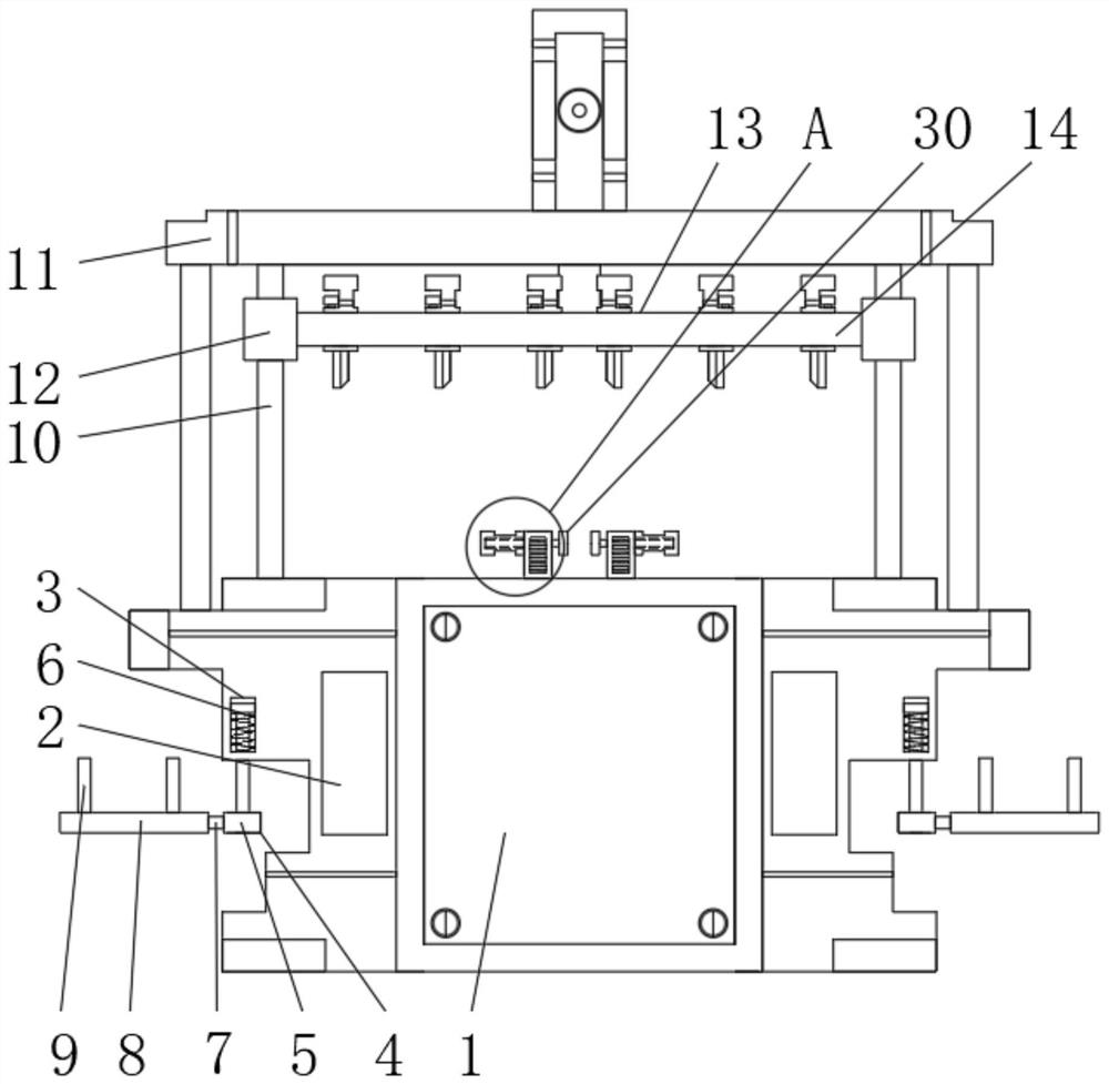
[0004] The purpose of the present invention is to provide a new type of rapid prototyping gear processing equipment for the production of bearing ring gears, to solve the problems caused by the existing gear processing equipment proposed in the above background technology because its end is not designed with a better flexible structure. When it is in use, it is impossible to adjust the machining distance of the teeth, and the adaptability and adjustment performance is poor, resulting in poor processing effect, and the ring gear cannot be placed and fixed well during processing, resulting in poor stability during processing and poor processing accuracy. lower

Method used


Image

  • Novel rapid forming tooth machining equipment for bearing gear ring production
  • Novel rapid forming tooth machining equipment for bearing gear ring production
  • Novel rapid forming tooth machining equipment for bearing gear ring production

Examples


Embodiment Construction

[0027] The following will clearly and completely describe the technical solutions in the embodiments of the present invention with reference to the accompanying drawings in the embodiments of the present invention. Obviously, the described embodiments are only some, not all, embodiments of the present invention.

[0028] In the description of the present invention, unless otherwise stated, the meaning of "plurality" is two or more; the terms "upper", "lower", "left", "right", "inner", "outer" , "front end", "rear end", "head", "tail", etc. indicate the orientation or positional relationship based on the orientation or positional relationship shown in the drawings, and are only for the convenience of describing the present invention and simplifying the description, rather than Nothing indicating or implying that a referenced device or element must have a particular orientation, be constructed, and operate in a particular orientation should therefore not be construed as limiting ...


PUM


Abstract

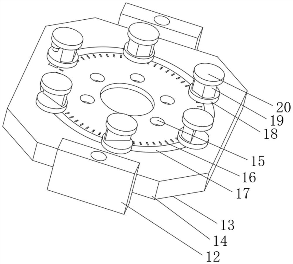
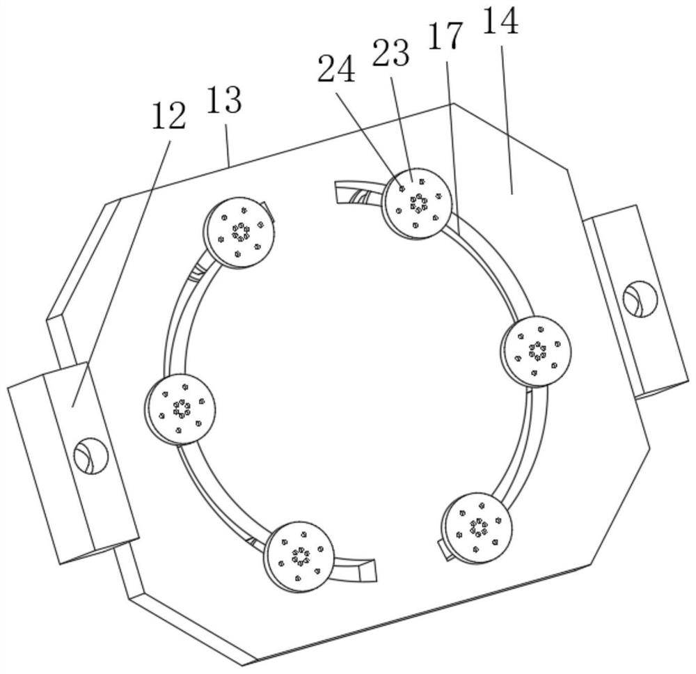
The invention relates to a novel rapid forming tooth machining equipment for bearing gear ring production. The novel rapid forming tooth machining equipment for bearing gear ring production comprises a tooth machining body and a lower bearing mechanism; the left end wall and the right end wall of the tooth machining body are each provided with a tooth box cavity and a tooth replacement separation groove in a penetrating mode; the lower bearing mechanism is arranged at the inner side end of the tooth replacement separation groove; movable rods are fixed to the tops of the left end and the right end of the tooth machining body; a rod upper disc is arranged at the top end of each movable rod; and a disc movable block is installed on the outer side of the movable rod. The novel rapid forming tooth machining equipment for bearing gear ring production has the following beneficial effects: a disc receiving disc and a clamping disc can be connected through a disc ring channel, so that annular movement can be performed in the disc ring channel, and flexible adjustment and use are facilitated; meanwhile, a positioning screw can be rotated, so that the positioning screw penetrates into the disc receiving disc to be tightly attached to the lower disc, locking is conducted, and firm placement and use can be carried out; and a cutting knife is fixed to the bottom of the clamping disc in a welded mode, when the clamping disc is pressed downwards, the cutting knife is pressed downwards along with the clamping disc, and gear ring cutting machining operation is conducted on the bearing carried on the body.

Description

technical field [0001] The invention relates to the technical field of bearing ring gear production, in particular to a new type of rapid prototyping gear processing equipment for bearing ring gear production. Background technique [0002] Bearings are an important part of contemporary mechanical equipment. Its main function is to support the mechanical rotating body, reduce the friction coefficient during its movement, and ensure its rotation accuracy. Among them, the ring gear in the bearing needs to use gear processing equipment during production and processing. [0003] Due to the fact that the end of the existing gear processing equipment is not designed with a good flexible structure, it is impossible to adjust the gear processing distance when it is used, and the adaptability and adjustment performance is poor, resulting in poor processing effect, and its ring gear is processing Due to the inability to place and fix well, the stability performance during processing i...

Claims


Application Information

Patent Timeline
Patent Type & Authority Applications(China)
IPC IPC(8): B23F17/00B23F23/06B23F23/12B23Q11/10
CPCB23F17/00B23F23/06B23F23/12B23Q11/10
Inventor 易阳
Owner WUXI YITONG PRECISION MACHINERY
Learn More