
Blade driving device

A driving device and blade technology, which is applied to the structure of telephones, filters for photography, optics, etc., can solve the problems of reduced prevention function, inability to obtain images, and camera function work.

Pending Publication Date: 2021-07-02
COPAL CO LTD
View PDF0 Cites 0 Cited by
  • Summary
  • Abstract
  • Description
  • Claims
  • Application Information

AI Technical Summary

Problems solved by technology

[0003] Regarding electronic equipment with a camera function, there are many electronic equipment in which the lens opening of the camera module mounted on the electronic equipment is always open. Therefore, in the IoT, if the camera function operates due to malicious external image, the outflow of private images or the reduction of the prevention function due to illegal image acquisition
[0004] In addition, when using a portable information terminal such as a PC or a smartphone, the camera function may be activated due to an operation error not intended by the user.
In such a case, there is also a problem that an image that the user does not want is taken into the electronic device and recorded, and the recorded image is suspected of being secretly photographed due to the external outflow of the recorded image or the recording of the unwanted image.
However, when the shielding member is manually operated, the opening and closing state of the shielding member is easily interrupted. Even if the user intends to close the lens opening and slides the shielding member, sometimes the shielding member will stop without completely covering the lens opening. You will notice this, and on the contrary, even if the user intends to open the lens opening and slides the shielding part, the shielding part will stop without completely disengaging from the lens opening, and the user will not notice this.
[0008] If it becomes such a situation, when the camera function is not used, an image that the user does not want may be taken into the electronic device from the partially opened lens opening. In addition, when the camera function is used, a part of the lens opening is closed, resulting in The problem that the desired image cannot be obtained
In addition, if the shielding member can be electrically operated in order to avoid such a problem, the operation of the shielding member itself may be externally operated due to unauthorized access, so it cannot be an effective countermeasure against unauthorized access.

Method used


Image

  • Blade driving device
  • Blade driving device
  • Blade driving device

Examples


Embodiment Construction

[0026] Hereinafter, embodiments of the present invention will be described with reference to the drawings. In the following description, the same reference numerals in different drawings denote parts with the same functions, and overlapping descriptions in each drawing are appropriately omitted.

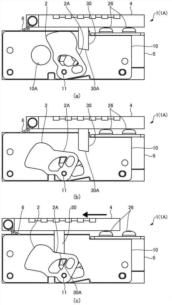
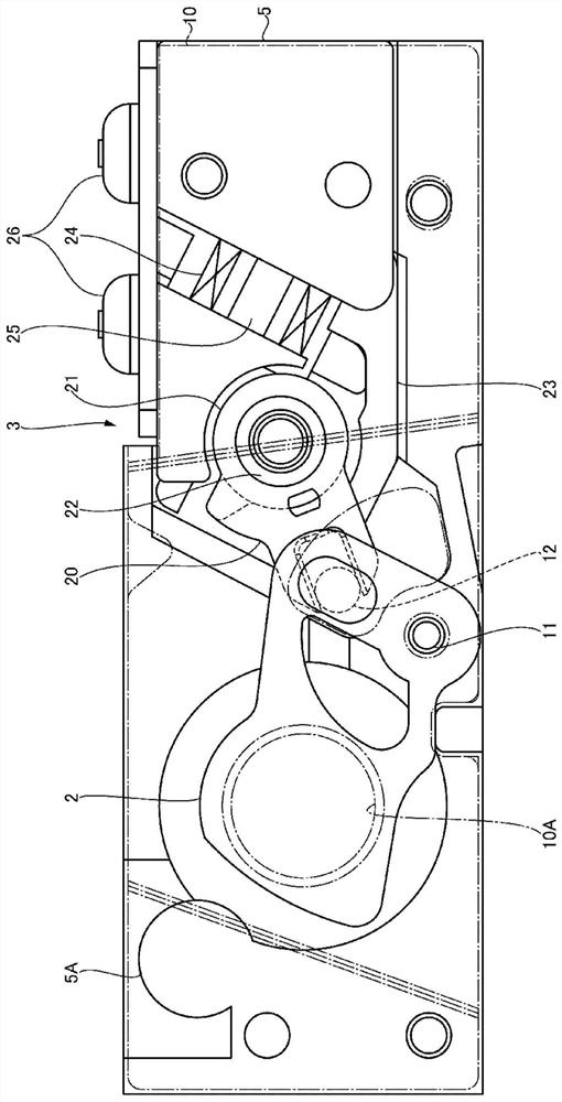
[0027] Such as figure 1 and figure 2 As shown, the blade driving device 1 (1A) includes blade parts 2, figure 2 The driving part 3 and the operating part 4 are shown. The blade member 2 , the drive unit 3 and the operation member 4 are mounted on the frame body 5 .

[0028] The housing 5 has an opening plate 10 having an opening 10A corresponding to the lens opening of the camera. Blade parts 2 such as figure 1 As shown in (a), the opening of the camera lens is opened by opening the opening 10A, as figure 1 of (b), figure 1 As shown in (c), the lens opening of the camera is in a shielded state by shielding the opening 10A. In the following description, the state in which th...


PUM


Abstract

The present invention provides a blade driving device, in an electronic device having a camera function, an image undesired by a user is prevented from being taken into the electronic device due to unauthorized access or user misoperation. The blade driving device has: a blade part that shields or opens the lens opening of the camera; a driving part that drives the blade member to a shielded state and an open state; and a manual operating part that is operated to prevent the movement of the blade part by the drive unit, the operating part can selectively move between the first position that prevents the movement of the blade part and the second position that does not prevent movement of the blade part.

Description

technical field [0001] The invention relates to a blade driving device. Background technique [0002] In recent years, many electronic devices have functions of processing, storing, and transmitting acquired images, and generally have a camera function (camera module) for acquiring images. In addition, in recent years, electronic devices, as represented by the term "IoT: Internet of Things (Internet of Things)", are used in a state connected to the network. Countermeasures against illegal access become indispensable. [0003] Regarding electronic equipment with a camera function, there are many electronic equipment in which the lens opening of the camera module mounted on the electronic equipment is always open. Therefore, in the IoT, if the camera function operates due to malicious external There are problems such as leakage of private images or reduction of the prevention function due to illegal image acquisition. [0004] In addition, when using a portable information ...

Claims


Application Information

Patent Timeline
IPC IPC(8): G03B11/04G06F1/16H04M1/02
CPCG03B11/041G06F1/1686H04M1/0264
Inventor 大野真理泽登孝司渡部伸昭
Owner COPAL CO LTD
Learn More