Stator permanent magnet type mover iron core block type linear oscillation motor and unit group

A mover iron core and oscillating motor technology, applied in the direction of electric components, electrical components, magnetic circuit shape/style/structure, etc., can solve problems such as limiting the stability of the mover's linear reciprocating motion, and the resonance frequency of the motor system is limited. Achieve the effect of avoiding irreversible mechanical failure, avoiding irreversible demagnetization, and facilitating heat dissipation

Active Publication Date: 2021-06-29
HUAZHONG UNIV OF SCI & TECH
View PDF4 Cites 0 Cited by
  • Summary
  • Abstract
  • Description
  • Claims
  • Application Information

AI Technical Summary

Problems solved by technology

The current moving iron type linear oscillating motor has a large mass of the mover, which limits the resonant frequency of the motor system, and the larger mass of the mover requires a resonant spring with a larger elastic coefficient, which limits the stability of the linear reciprocating motion of the mover sex

Method used


Image

  • Stator permanent magnet type mover iron core block type linear oscillation motor and unit group
  • Stator permanent magnet type mover iron core block type linear oscillation motor and unit group
  • Stator permanent magnet type mover iron core block type linear oscillation motor and unit group

Examples


Embodiment Construction

[0042] In order to make the object, technical solution and advantages of the present invention clearer, the present invention will be further described in detail below in conjunction with the accompanying drawings and embodiments. It should be understood that the specific embodiments described here are only used to explain the present invention, not to limit the present invention. In addition, the technical features involved in the various embodiments of the present invention described below can be combined with each other as long as they do not constitute a conflict with each other.

[0043] In the present invention, the terms "first", "second" and the like (if any) in the present invention and drawings are used to distinguish similar objects, and are not necessarily used to describe a specific order or sequence.

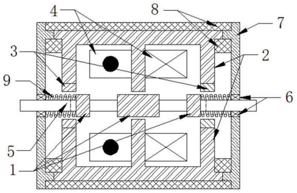
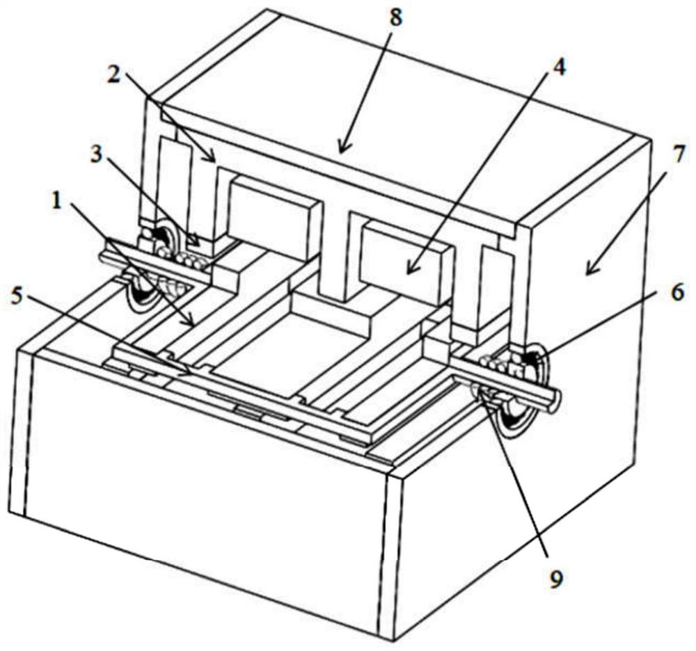
[0044] figure 1 It is a schematic diagram of the longitudinal section structure of the stator permanent magnet type mover iron core segmented linear oscillation m...


PUM


Abstract

The invention discloses a stator permanent magnet type mover iron core block type linear oscillation motor and a unit group, and belongs to the field of linear oscillation motors. The motor comprises a block type mover iron core which comprises a plurality of mover iron cores separated from one another, a stator iron core which comprises two parts symmetrically distributed on the two sides of the motion plane of the block type mover iron core, a permanent magnet which is surface-mounted on the surfaces of the stator teeth located at the end part in the stator core, and an armature winding which comprises two groups of coils which are respectively wound on two stator teeth in the middle in the stator iron core, wherein each part of the stator iron core comprises stator teeth and a stator yoke part. When a sine alternating current is introduced into the armature winding, a sine-like electromagnetic thrust is generated in the block type mover iron core to push the block type mover iron core to do reciprocating linear oscillation motion. The mass of the mover is reduced and the resonant frequency and the power density of the system are improved through the block type mover iron core, the permanent magnet is attached to the stator end teeth, a permanent magnet sheath can be prevented from being installed, a mechanical air gap is reduced to enhance coupling between the stator and the mover, and heat dissipation of the permanent magnets is facilitated.

Description

technical field [0001] The invention belongs to the field of linear oscillating motors, and more specifically relates to a stator permanent magnet type mover iron core segmented linear oscillating motor and a unit group. Background technique [0002] Linear oscillating motors can be divided into linear asynchronous oscillating motors and linear synchronous oscillating motors according to whether there is a gap between the moving speed of the mover and the moving speed of the traveling wave magnetic field. Among them, the linear synchronous oscillating motor usually only needs a single-phase winding, relies on the electromagnetic force and the resonance of the resonant spring to generate a linear reciprocating motion strictly controlled by the frequency of the input AC, and has performance advantages such as low loss, high efficiency, and large thrust. It is used in linear compressors. fields are widely used. [0003] The moving iron linear synchronous oscillating motor gene...

Claims


Application Information

Patent Timeline
IPC IPC(8): H02K1/17H02K1/18H02K1/14H02K33/18H02K41/03
CPCH02K1/17H02K1/18H02K1/14H02K33/18H02K41/033H02K2213/03
Inventor 徐伟张娅平张祎舒
Owner HUAZHONG UNIV OF SCI & TECH
Why Eureka
Try Eureka