
Rotor blade of a wind turbine, comprising an insulator layer and a protective layer

A technology of rotor blades and wind energy equipment, which is applied in wind energy generation, mechanical equipment, conductor discharge/power consumption, etc., and can solve problems such as damage

Pending Publication Date: 2021-06-25
西门子加美萨可再生能源服务有限公司
View PDF1 Cites 1 Cited by
  • Summary
  • Abstract
  • Description
  • Claims
  • Application Information

AI Technical Summary

Problems solved by technology

[0006] It has been shown here that damage to the belt can still occur during a lightning strike

Method used


Image

  • Rotor blade of a wind turbine, comprising an insulator layer and a protective layer
  • Rotor blade of a wind turbine, comprising an insulator layer and a protective layer
  • Rotor blade of a wind turbine, comprising an insulator layer and a protective layer

Examples


Embodiment Construction

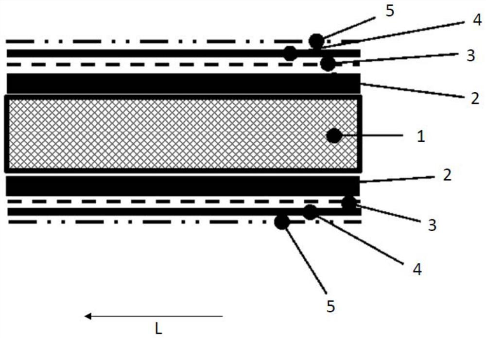
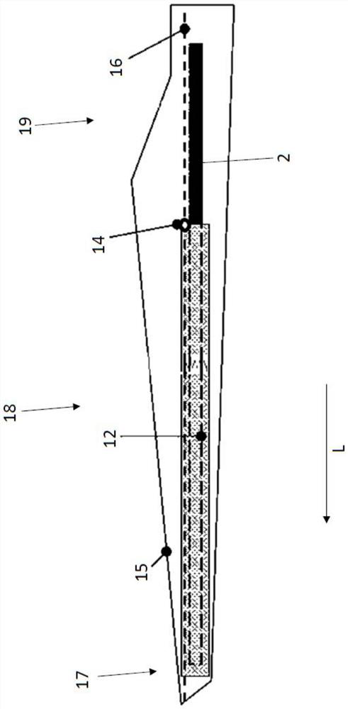
[0029] figure 1 A schematic view of a portion of a longitudinal section of a rotor blade 15 along a web 1 , in particular a main web, is shown. The web 1 is arranged between the rotor blade surface 5 on the suction side and the pressure side. The rotor blade surface 5 delimits the respective suction-side or pressure-side rotor blade half shell to the outside. figure 1 The structure in is mirror-symmetrical, and layers and features on the suction and pressure sides are denoted by the same reference numerals.

[0030] The rotor blade half-shells consist of a laminated structure with an electrically conductive protective layer 4 on the rotor blade surface 5 on the rotor blade inner side, the electrically conductive protective layer 4 being formed according to figure 1 Embodiments of the present invention comprise carbon fibers, or even consist entirely of carbon fibers. The protective layer 4 can form the outermost layer of the rotor blade half-shell, but it is also conceivabl...


PUM


Abstract

The invention relates to a rotor blade of a wind turbine, comprising at least one belt (2), and at least one protective layer (4) that is positioned on the at least one belt (2) on the rotor blade outer side, said at least one protective layer (4) being designed to be electrically conductive and connected to a lightening conduction element (16), wherein at least one electrically insulating insulator layer (3) is arranged between the at least one protective layer (4) and the at least one belt (2).

Description

technical field [0001] The invention relates to a rotor blade of a wind energy installation, comprising: at least one strip; at least one protective layer arranged on the at least one strip on the outer side of the rotor blade, wherein the at least one protective layer is formed as Conductive and connected to a lightning arrester. The invention also relates to a method for producing a rotor blade of a wind energy installation, wherein at least one electrically conductive protective layer is arranged on at least one strip on the outer side of the rotor blade and is connected to a surge arrester. Background technique [0002] Rotor blades with bands are already known in the prior art. In principle, the rotor blade can consist of a rotor blade shell, which in turn advantageously consists of two rotor blade half shells. The band extends in the longitudinal direction of each of the rotor blade half-shells. The two straps face each other and the web is guided along between the ...

Claims


Application Information

Patent Timeline
Patent Type & Authority Applications(China)
IPC IPC(8): F03D80/30F03D1/06
CPCF03D80/30F03D1/0675F03D1/06F05B2280/2006Y02E10/72F05B2280/6003H02G13/80
Inventor 俄斯·班德尔
Owner 西门子加美萨可再生能源服务有限公司
Learn More