
Oscillating head mechanism of oscillating rolling machine

A technology of swinging mill and swinging head, which is applied in forging/pressing/hammering machinery, manufacturing tools, forging/pressing/hammer devices, etc., can solve the problems of reduced sealing effect and oil leakage, and achieves reasonable structural design and improved The effect of oil sealing effect

Pending Publication Date: 2021-06-25
宁波铭匠智能设备有限责任公司
View PDF0 Cites 0 Cited by
  • Summary
  • Abstract
  • Description
  • Claims
  • Application Information

AI Technical Summary

Problems solved by technology

[0002] Oscillating rolling is a new plastic forming method. Limiting the contact area between the tool and the blank can reduce the deformation force, so that a smaller force can be used to gradually form a larger workpiece. It has labor-saving, small impact, and small vibration. , low noise, energy saving and material saving, and high product precision, it is widely used in many industrial fields such as machinery, automobiles, electrical appliances, instruments, hardware tools, etc.; However, in the case of long-term oscillating operation, the sealing effect will be reduced, and oil leakage will occur; or the oil receiving part that is open on the side of the oscillating head is limited by the swing of the oscillating head, and oil leakage will also occur.

Method used


Image

  • Oscillating head mechanism of oscillating rolling machine
  • Oscillating head mechanism of oscillating rolling machine
  • Oscillating head mechanism of oscillating rolling machine

Examples


Embodiment Construction

[0079] The specific implementation manners of the present invention will be further described in detail below in conjunction with the accompanying drawings and embodiments. The following examples are used to illustrate the present invention, but are not intended to limit the scope of the present invention.

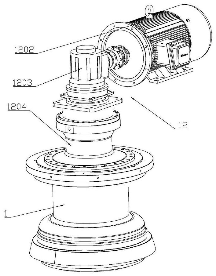
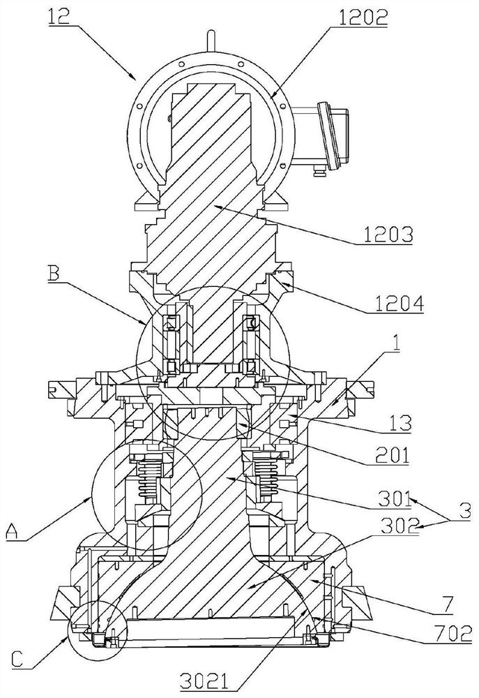
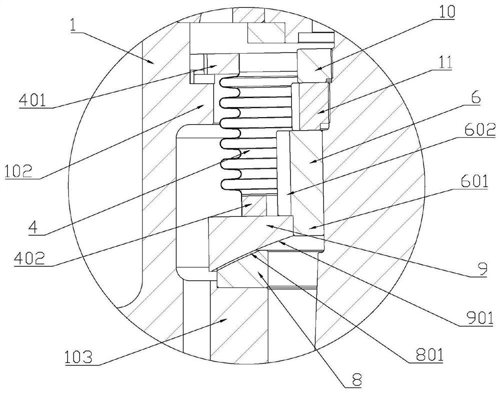
[0080] Such as figure 1 As shown in -15, a oscillating head mechanism of a oscillating mill includes a host housing 1 provided with an accommodating cavity 101, an oscillating head assembly 3, and an oil receiving member 18; Inside the accommodating chamber 101; the accommodating chamber 101 forms a first opening 104 on the end face of the main engine casing 1 for exposing the swing head 302 of the swing head assembly 3; The swing head connecting part 1801 connected with the head 302, and the oil receiving concave part 1802 arranged under the entire peripheral edge of the first opening 104, one end of the oil receiving concave part 1802 is connected with the swing head co...


PUM


Abstract

The invention discloses an oscillating head mechanism of an oscillating rolling machine. The oscillating head mechanism of the oscillating rolling machine comprises a main machine shell provided with a containing cavity, an oscillating head assembly and an oil receiving piece. The oscillating head assembly is mounted in the containing cavity in an oscillating manner; the containing cavity forms a first opening in the end surface of the main machine shell; the first opening is used for exposing the oscillating head of the oscillating head assembly; the oil receiving piece comprises an oscillating head connecting part used for being connected with the oscillating head, and an oil receiving concave part arranged below the whole peripheral edge of the first opening; one end of the oil receiving concave part is connected with the oscillating head connecting part; and at least part of the oil receiving concave part can deform. According to the oscillating head mechanism of the oscillating rolling machine provided by the invention, the oil receiving piece and the oscillating head are fixed in a closed mode, and the oil receiving piece is prevented from influencing oscillation of the oscillating head by means of deformation.

Description

technical field [0001] The invention relates to the field of oscillating mills, in particular to an oscillating mechanism of the oscillating mill. Background technique [0002] Oscillating rolling is a new plastic forming method. Limiting the contact area between the tool and the blank can reduce the deformation force, so that a smaller force can be used to gradually form a larger workpiece. It has labor-saving, small impact, and small vibration. , low noise, energy saving and material saving, and high product precision, it is widely used in many industrial fields such as machinery, automobiles, electrical appliances, instruments, hardware tools, etc.; However, in the case of long-term swing operation, the sealing effect is reduced, and oil leakage occurs; or the oil receiving part is adopted to open the swing head side due to the limitation of the swing of the swing head, and oil leakage also occurs. Contents of the invention [0003] In order to overcome the deficiencie...

Claims


Application Information

Patent Timeline
Patent Type & Authority Applications(China)
IPC IPC(8): B21J13/00
CPCB21J13/00
Inventor 孟繁东罗邦才
Owner 宁波铭匠智能设备有限责任公司
Learn More