Method and device for determining trigger point of flying shooting

A technology for determining methods and trigger points, which is applied in the field of visual inspection and can solve problems such as labor-intensive

Active Publication Date: 2022-05-27
CHANGZHOU MICROINTELLIGENCE CO LTD
View PDF0 Cites 0 Cited by
  • Summary
  • Abstract
  • Description
  • Claims
  • Application Information

AI Technical Summary

Problems solved by technology

If a manual method is used to measure and compensate for this deviation, it will take a lot of manpower

Method used


Image

  • Method and device for determining trigger point of flying shooting
  • Method and device for determining trigger point of flying shooting
  • Method and device for determining trigger point of flying shooting

Examples


Embodiment Construction

[0021] The technical solutions in the embodiments of the present invention will be clearly and completely described below with reference to the accompanying drawings in the embodiments of the present invention. Obviously, the described embodiments are only a part of the embodiments of the present invention, rather than all the embodiments. Based on the embodiments of the present invention, all other embodiments obtained by those of ordinary skill in the art without creative efforts shall fall within the protection scope of the present invention.

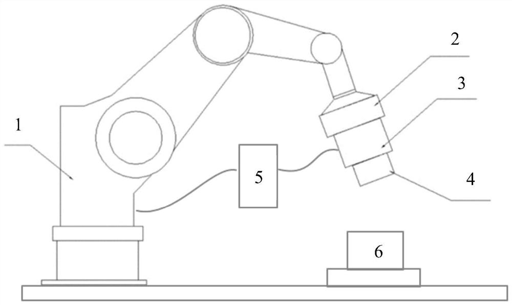
[0022] like figure 1 As shown, the fly-shooting device in the embodiment of the present invention may include a robotic arm 1, a camera support 2, a camera 3 and a light source 4 disposed at the end of the robotic arm 1, and an operational A computing power machine 5 that controls the program. The robotic arm 1 , the camera support 2 , the camera 3 and the light source 4 can be set corresponding to the platform 6 on which the workpi...


PUM


Abstract

The present invention provides a method and device for determining a trigger point for fly-by-shot shooting. The method includes the following steps: S1, obtaining a first image by static shooting at the shooting point; S2, intercepting a sub-image in the first image; S3, at During the flying shooting process, a trigger signal is sent to the camera at the undetermined shooting trigger point corresponding to the shooting point to obtain the second image; S4, template matching is performed in the second image by using the sub-image as a template to obtain the target in the second image object; S5, obtain the coordinate information of the sub-image in the first image and the coordinate information of the target object in the second image, and calculate the positional deviation of the target object in the second image and the sub-image in the first image; S6, Adjust the to-be-determined shooting trigger point according to the position deviation to obtain the actual shooting trigger point. The invention can conveniently and effectively quantitatively determine the deviation between the flying-shot image and the actual demand image, so that the shooting trigger point of the camera in the flying-shooting process can be conveniently and accurately determined.

Description

technical field [0001] The present invention relates to the technical field of visual inspection, and in particular to a method for determining a trigger point for flying photography, a device for determining a trigger point for flying photography, a computer device and a non-transitory computer-readable storage medium. Background technique [0002] In the traditional process of visual inspection using industrial cameras, the industrial camera is fixed at the end of the robotic arm. When the workpiece to be inspected is transferred to the shooting position, the robotic arm moves the camera to the workpiece shooting point, and stops the movement for static shooting. Next, in the same way, the robotic arm carries the camera to perform static photography of the next point until all the locations to be photographed are photographed. In this process, the industrial camera needs to stop moving every time it reaches the shooting point, resulting in a long shooting cycle and low eff...

Claims


Application Information

Patent Timeline
Patent Type & Authority Patents(China)
IPC IPC(8): H04N5/232
CPCH04N23/64
Inventor 顾徐波王闯马元巍潘正颐侯大为
Owner CHANGZHOU MICROINTELLIGENCE CO LTD
Why Eureka
Try Eureka