Multi-depth camera rapid calibration and data fusion method

A technology of data fusion and calibration method, applied in the field of 3D vision, can solve the problems of data fusion error, the data collected by the camera cannot be synchronized, and achieve the effect of reducing the matching error and improving the fusion accuracy.

Pending Publication Date: 2021-06-22
NANJING STARTON MEDICAL TECH CO LTD
View PDF0 Cites 0 Cited by
  • Summary
  • Abstract
  • Description
  • Claims
  • Application Information

AI Technical Summary

Problems solved by technology

[0004] The present invention proposes a method for rapid calibration and data fusion of multi-depth cameras, which solves the problem of calibration of multi-depth cameras in applications, and when the measured object is in motion, the data collected by the cameras cannot be synchronized, resulting in data fusion errors

Method used


Image

  • Multi-depth camera rapid calibration and data fusion method
  • Multi-depth camera rapid calibration and data fusion method
  • Multi-depth camera rapid calibration and data fusion method

Examples


Embodiment 1

[0049] Embodiment 1 quick calibration

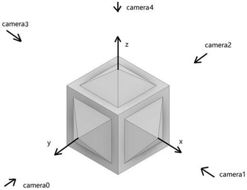
[0050] Calibrator and its location such as image 3As shown, the calibration object is based on a cube, and a pyramid-shaped shape is arranged in the center of the five faces. The four faces of the pyramid are exactly the same, and the angle between each face and the plane is 106 degrees.

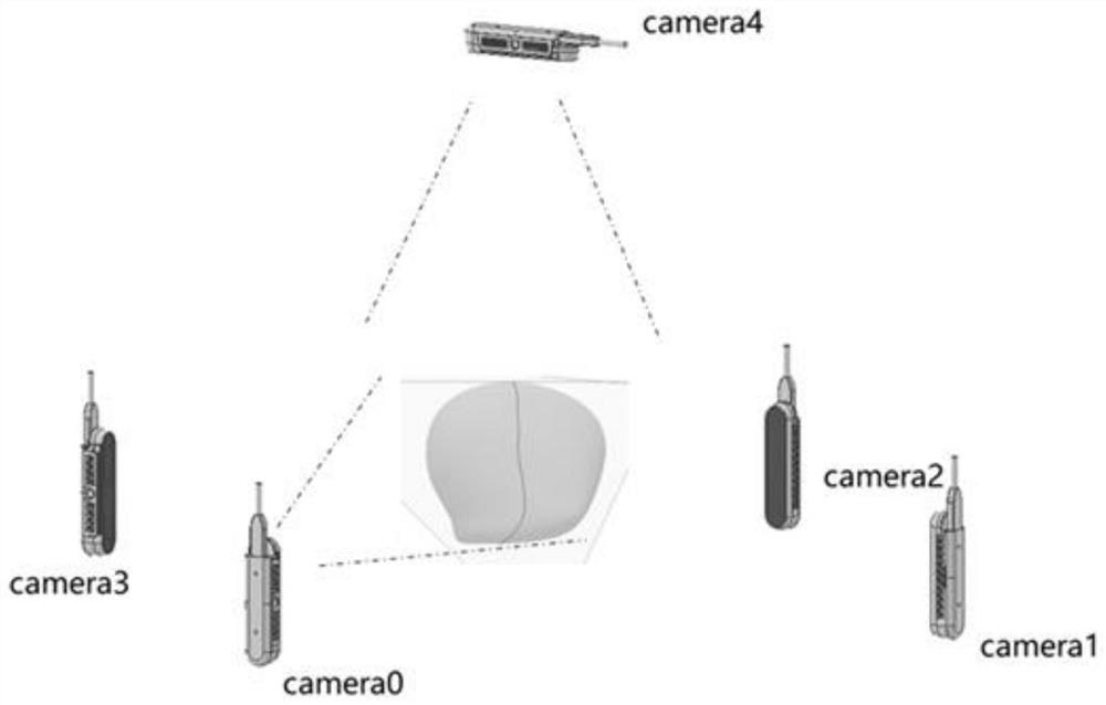
[0051] When calibrating, first place the calibration object in the middle determined by the five cameras (camera0, camera1, camera2, camera3, camera4), each face of the calibration object faces the camera, and when the calibration object is still, the five cameras take turns To collect data, each camera takes turns collecting once in each round, repeating multiple rounds, and then performing calibration calculations to complete the calibration.

[0052] The principle is as follows:

[0053] a) The system itself determines a defective local coordinate system, as follows: the y-axis of the local coordinate system points to camera0 (camera 0) in the po...

Embodiment 2

[0084] Example 2 Dynamic matching-fusion

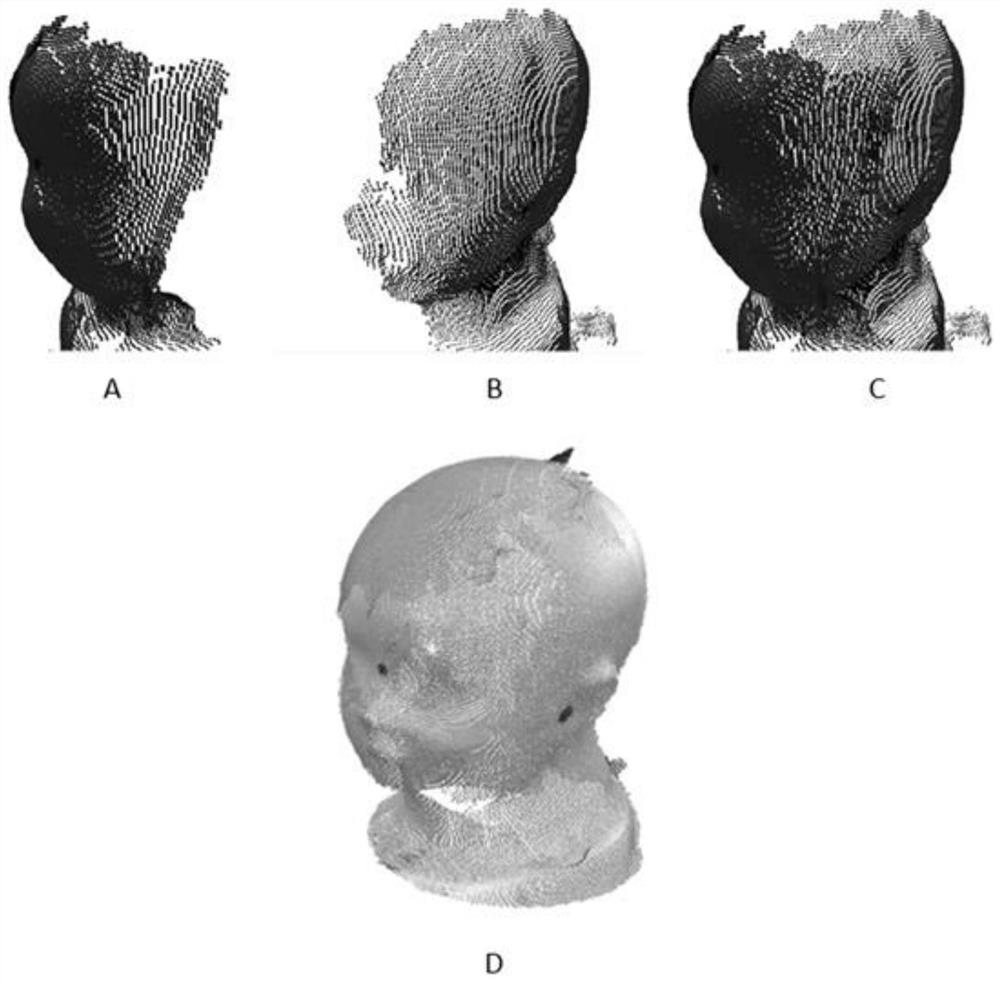
[0085] In view of the fact that the measured object cannot be completely still during measurement, and when the cameras of the scanner collect data, the cameras with mutual interference cannot be activated at the same time, and need to be carried out in time, resulting in the data collected by each camera not being synchronized with the target at a fixed position data. Even when the calibration is completely accurate, data fusion errors will result. To solve this problem, the present invention proposes a method for matching RBG color images and depth data of integrated cameras to reduce multi-camera point cloud fusion errors.

[0086] Principle description:

[0087] a) In this application example, the top camera 4 is used as the reference camera, and other four cameras can also be selected as the reference camera.

[0088] b) Stick three red marking dots on the top of the target facing the camera 4, these dots are easily recognized ...


PUM


Abstract

The invention provides a multi-depth camera rapid calibration and data fusion method, and belongs to the technical field of 3D vision. According to the structure of the calibration object, a pyramid structure is arranged in the middle of each of the four side faces and the top face of a cube, each pyramid structure comprises a plurality of planes, and the included angle between each plane and the corresponding plane is larger than 90 degrees so that it can be guaranteed that a depth camera can obtain information of each plane, data of the planes can be fitted, and the calibration object can be obtained. And obtaining an intersection line of the surfaces. And the space coordinate of the intersection line obtained by each camera is matched with an actual calibration object, so that the space calibration of the external parameters of the camera is realized. According to the method, data fusion is carried out by taking the data of one main camera as a reference, collecting the data in groups, carrying out dynamic matching and fitting and adopting a method of eliminating errors by adopting point clouds of a matched public area, so that data errors among multiple cameras caused by movement of a measured object are greatly reduced, and the precision of data fusion is improved.

Description

technical field [0001] The invention relates to the technical field of 3D vision, in particular to a multi-depth camera calibration and data fusion method. Background technique [0002] Depth camera is a new measurement and imaging technology developed in recent years. This type of camera provides three-dimensional point cloud data while giving color images in the field of view. These point cloud data represent the spatial information (x, y, z) in the measured scene , through these point cloud data, the 3D data of the measured object in the field of view can be obtained. In order to obtain all-round 3D data of an object, multiple cameras are usually used to obtain the 3D data of the object from different angles and orientations, and then the data are fused to obtain the 3D data of the measured object. However, the data obtained by each camera corresponds to the spatial position of the camera. To integrate these data, the spatial position (spatial coordinates + direction) of...

Claims


Application Information

Patent Timeline
Patent Type & Authority Applications(China)
IPC IPC(8): G06T7/80G06T17/00
CPCG06T7/85G06T17/00G06T2207/10012
Inventor 王玉飞王维平
Owner NANJING STARTON MEDICAL TECH CO LTD
Why Eureka
Try Eureka