A chainless transmission mechanism

A transmission mechanism, chainless technology, applied in the direction of transmission, gear transmission, mechanical equipment, etc., can solve the problems of huge machines, increased production costs, and bulkiness

Active Publication Date: 2022-03-11
JIANGXI EQUIP INDAL GROUP GREAT INSURANCENT
View PDF7 Cites 0 Cited by
  • Summary
  • Abstract
  • Description
  • Claims
  • Application Information

AI Technical Summary

Problems solved by technology

[0004] In order to overcome the fact that the general transmission mechanism can only change one of its direction, speed and mode, multiple transmission mechanisms need to be used in one machine, which makes the machine too bulky and heavy, and will increase the production cost, which is not conducive to the machine Shortcomings in production and manufacturing, technical problems to be solved: provide a chainless transmission mechanism capable of changing the direction, speed and mode of power

Method used


Image

  • A chainless transmission mechanism
  • A chainless transmission mechanism
  • A chainless transmission mechanism

Examples


Embodiment 1

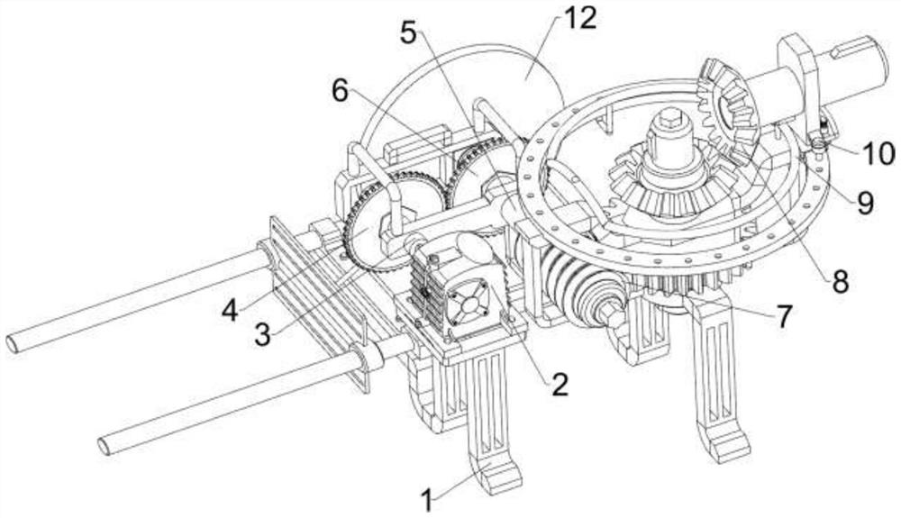
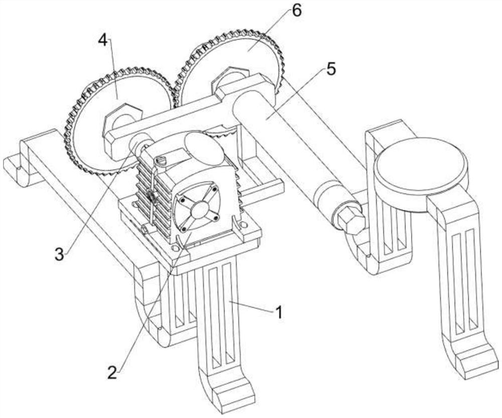
[0026] A chainless transmission mechanism, such as Figure 1-4 As shown, it includes a support 1, a motor 2, a first rotating shaft 3, a first gear 4, a second rotating shaft 5, a second gear 6, a deceleration assembly 7 and a transmission direction changing assembly 8, and there are two support 1, the left The upper side of the side support 1 is provided with a motor 2, the output shaft of the motor 2 is connected with a first rotating shaft 3, the first rotating shaft 3 is connected with the left side support 1 in a rotating manner, and the rear side of the first rotating shaft 3 is connected with The first gear 4, the right side of the left support 1 is rotationally connected with the second rotating shaft 5, the rear side of the second rotating shaft 5 is connected with the second gear 6, the second gear 6 meshes with the first gear 4, and the right side A deceleration assembly 7 is provided between the bracket 1 and the second rotating shaft 5 , and a transmission directi...

Embodiment 2

[0033] On the basis of Example 1, such as figure 1 , Figure 4 , Figure 5 , Figure 6 As shown, a separation assembly 9 is also included, the separation assembly 9 includes a special-shaped ring 91 and a push rod 93, the fixed ring 81 is connected with a special-shaped ring 91, the upper side of the left part of the special-shaped ring 91 has a limiting groove 92, and a sliding plate 83 The left side of the top is connected with a push rod 93, and the push rod 93 cooperates with the limit groove 92.

[0034]When there is no need to use the transmission direction changing assembly 8, the arc slider 82 can be controlled to move, so that the sliding plate 83 and the push rod 93 can move, and when the push rod 93 moves to the left side of the special-shaped ring 91, the special-shaped ring 91 will Make the push rod 93 move upwards, so that the sliding plate 83 moves upwards, and then the bevel gears 85 on both sides are no longer engaged. The bit groove 92 fixes the push rod ...


PUM


Abstract

The invention relates to a transmission mechanism, in particular to a chainless transmission mechanism. The technical problem to be solved by the present invention is to provide a chainless transmission mechanism capable of changing the direction, speed and mode of power. A chainless transmission mechanism, comprising: a bracket, two brackets; a motor, a motor is provided on one side of the bracket; a first rotating shaft, the output shaft of the motor is connected with the first rotating shaft, the first rotating shaft and One side bracket is connected in rotation; the first gear is connected with the first gear on the first rotation shaft; the second rotation shaft is connected with the second rotation shaft in rotation on the left side bracket; the second gear is connected with the second rotation shaft A second gear is connected, and the second gear meshes with the first gear. The present invention has a separation component, thereby fixing the arc-shaped slider, thereby preventing the arc-shaped slider from moving automatically and affecting the transmission effect.

Description

technical field [0001] The invention relates to a transmission mechanism, in particular to a chainless transmission mechanism. Background technique [0002] The transmission mechanism is a component or mechanism that transmits power from one part of the machine to another, and makes the machine or machine parts move or operate. Generally, the transmission mechanism can only transmit power to the designated part, and can only change one of its direction, speed and mode. Therefore, multiple transmission mechanisms are required in one machine, which makes the machine too bulky and heavy, and leads to The cost increases, which is not conducive to the production and manufacture of the machine. [0003] Therefore need to design a kind of chainless transmission mechanism with the direction, speed and mode that can change power. Contents of the invention [0004] In order to overcome the fact that the general transmission mechanism can only change one of its direction, speed and...

Claims


Application Information

Patent Timeline
Patent Type & Authority Patents(China)
IPC IPC(8): F16H3/06F16H3/14H02K7/116
CPCF16H3/06F16H3/145H02K7/1163H02K7/1166
Inventor 陈水才
Owner JIANGXI EQUIP INDAL GROUP GREAT INSURANCENT
Why Eureka
Try Eureka