
An efficient cleaning device for dispensing workbench for intelligent manufacturing

A technology for intelligent manufacturing and cleaning devices, which is applied in the direction of cleaning methods using tools, cleaning methods using liquids, cleaning methods and utensils. Effect

Active Publication Date: 2022-04-29
KINGWAY CHENZHOU ELECTRONICS
View PDF0 Cites 0 Cited by
  • Summary
  • Abstract
  • Description
  • Claims
  • Application Information

AI Technical Summary

Problems solved by technology

[0004] In order to overcome the disadvantages of many manual operations in the prior art, complex structure and inconvenient operation, the technical problem to be solved is to provide a high degree of automation, which can automatically clamp and release the workbench and is convenient Efficient cleaning device for dispensing workbench for intelligent manufacturing of people collecting workbench

Method used


Image

  • An efficient cleaning device for dispensing workbench for intelligent manufacturing
  • An efficient cleaning device for dispensing workbench for intelligent manufacturing
  • An efficient cleaning device for dispensing workbench for intelligent manufacturing

Examples


Embodiment 1

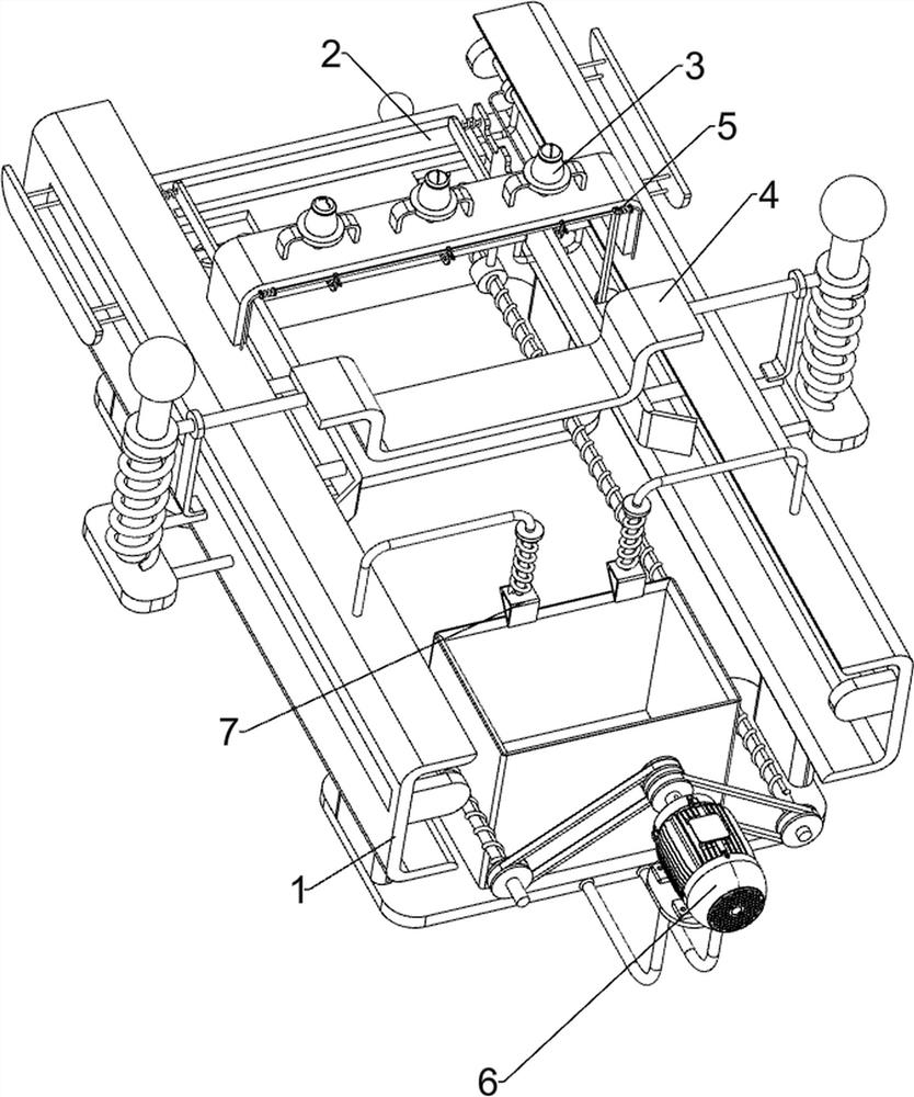
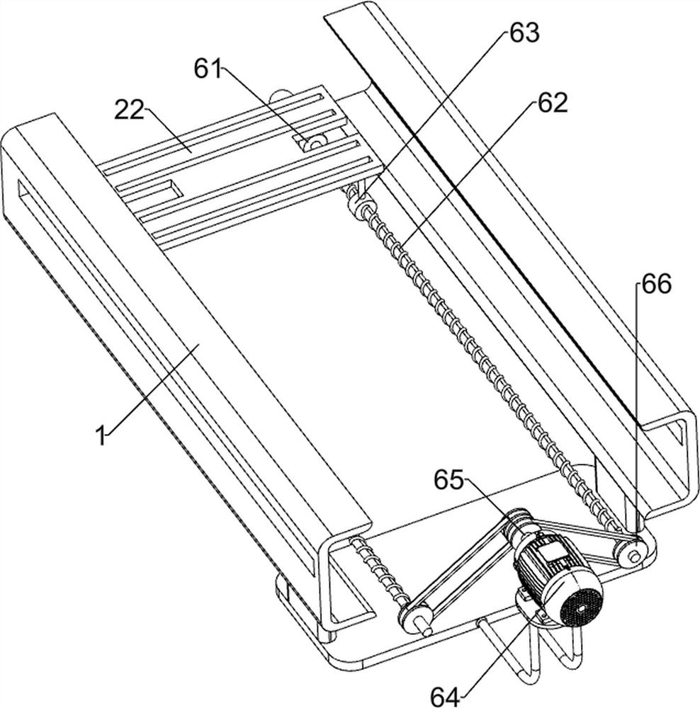
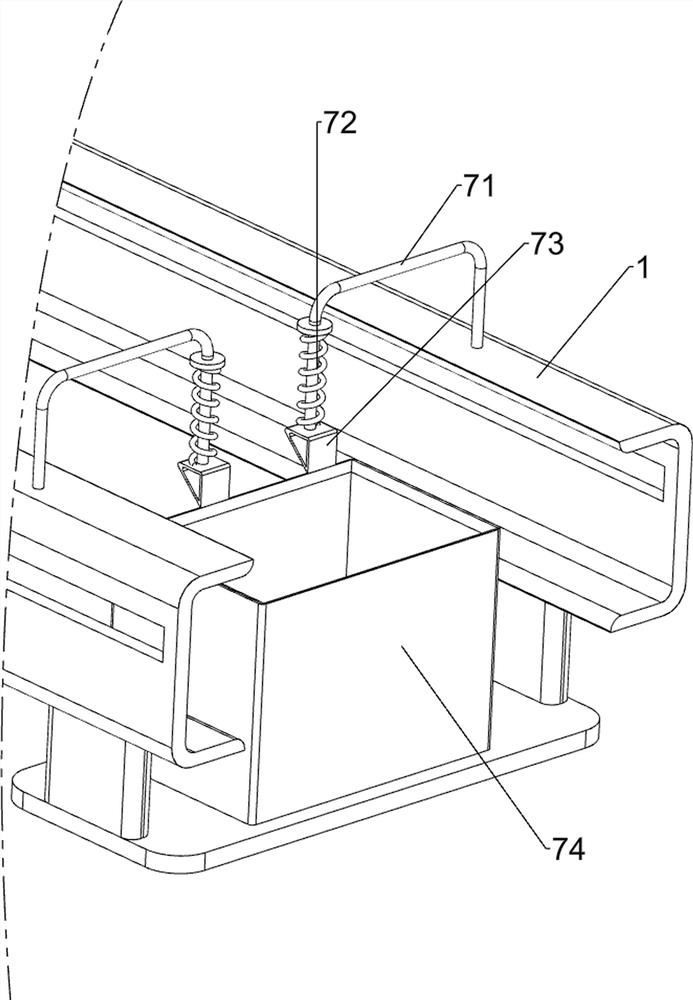
[0028] An efficient cleaning device for dispensing worktables for intelligent manufacturing, such as figure 1 , figure 2 , image 3 and Figure 4 As shown, a base 1, a fixing mechanism 2, a cleaning mechanism 3 and a wiping mechanism 4 are included, the base 1 is provided with a fixing mechanism 2, the base 1 is provided with a cleaning mechanism 3, and the base 1 is provided with a wiping mechanism 4 .

[0029] First, people place the dispensing workbench on the fixing mechanism 2, and add enough cleaning agent in the cleaning mechanism 3, and then people can push the fixing mechanism 2 to the right, so that the fixing mechanism 2 drives the workbench to move to the right, and at the same time through the fixing The cooperation between the parts of the mechanism 2 makes the fixing mechanism 2 clamp the workbench, and then when the workbench moves to the bottom of the cleaning mechanism 3, people can open the cleaning mechanism 3, so that the cleaning agent in the cleaning...

Embodiment 2

[0035] On the basis of Example 1, such as figure 1 , Figure 5 , Image 6 and Figure 7 As shown, it also includes a cleaning auxiliary mechanism 5, and the cleaning auxiliary mechanism 5 includes a second fixed rod 51, a third telescopic assembly 52, a first connecting rod 53, a fixed block 54, a connecting block 55, a top plate 56 and a push rod 57, basically The top of the left side of the seat 1 is symmetrically provided with a second fixed rod 51, the top of the second fixed rod 51 is provided with a third telescopic assembly 52, and a first connecting rod 53 is arranged between the third telescopic assembly 52. ​​On the first connecting rod 53 A plurality of fixing blocks 54 are provided, and connecting blocks 55 are arranged on the valve 34, and the connecting blocks 55 cooperate with the fixing blocks 54. A top plate 56 is arranged between the two first sliding sleeves 21 on the rear side, and a top plate 56 is arranged on the first connecting rod 53. A push rod 57 ...


PUM


Abstract

The invention relates to a cleaning device, in particular to an efficient cleaning device for dispensing workbenches for intelligent manufacturing. The invention provides a high-efficiency cleaning device for dispensing workbenches for intelligent manufacturing, which has a high degree of automation, can automatically clamp and loosen workbenches, and is convenient for people to collect workbenches. A high-efficiency cleaning device for dispensing workbenches for intelligent manufacturing, comprising: a base with a fixing mechanism; a cleaning mechanism with a cleaning mechanism on the base; and a wiping mechanism with a wiping mechanism on the base. The present invention realizes the placement and clamping of the workbench through the fixing mechanism, and then cooperates with the cleaning mechanism to make the cleaning agent fall on the workbench; through the cooperation of the fixing mechanism and the wiping mechanism, the wiping mechanism is automatically moved downwards, Thereby realize the automatic wiping of workbench.

Description

technical field [0001] The invention relates to a cleaning device, in particular to an efficient cleaning device for dispensing workbenches for intelligent manufacturing. Background technique [0002] When workers dispense glue on the product, they usually place the product on the workbench, and then use the dispenser to dispense glue on the product. However, it is inevitable that the glue will fall on the workbench during the dispensing process. In this way, people need to clean the workbench after the product is processed. However, manual cleaning has low cleaning efficiency and high labor intensity. However, the existing auxiliary cleaning devices are usually complicated in structure and require manual operation. There are many steps, and the workbench needs to be manually moved when cleaning, which is inconvenient in operation. [0003] Therefore, in view of the above shortcomings, we need to develop an efficient cleaning device for dispensing workbenches for intelligen...

Claims


Application Information

Patent Timeline
Patent Type & Authority Patents(China)
IPC IPC(8): B08B1/00B08B3/08B08B13/00
CPCB08B1/006B08B1/008B08B3/08B08B13/00
Inventor 岩龙
Owner KINGWAY CHENZHOU ELECTRONICS
Learn More