
Display module, manufacturing method of display module, and electronic device

A technology for display modules and manufacturing methods, which is applied in the direction of chemical instruments and methods, circuits, electrical components, etc., can solve problems affecting the display effect of display modules, and achieve the effect of improving the display effect

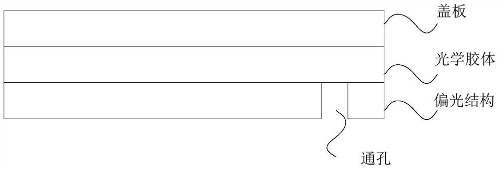
Active Publication Date: 2022-07-12
KUNSHAN NEW FLAT PANEL DISPLAY TECH CENT
View PDF2 Cites 0 Cited by
  • Summary
  • Abstract
  • Description
  • Claims
  • Application Information

AI Technical Summary

Problems solved by technology

According to the research of the inventors, based on the above-mentioned settings in the prior art, it is easy to generate bonding bubbles, which will affect the display effect of the display module

Method used


Image

  • Display module, manufacturing method of display module, and electronic device
  • Display module, manufacturing method of display module, and electronic device
  • Display module, manufacturing method of display module, and electronic device

Examples


Embodiment Construction

[0038] In order to make the purposes, technical solutions and advantages of the embodiments of the present application more clear, the technical solutions in the embodiments of the present application will be described clearly and completely below with reference to the drawings in the embodiments of the present application. Obviously, the described embodiments It is only a part of the embodiments of the present application, but not all of the embodiments. The components of the embodiments of the present application generally described and illustrated in the drawings herein may be arranged and designed in a variety of different configurations.

[0039] Thus, the following detailed description of the embodiments of the application provided in the accompanying drawings is not intended to limit the scope of the application as claimed, but is merely representative of selected embodiments of the application. Based on the embodiments in this application, all other embodiments obtaine...


PUM

PropertyMeasurementUnit
thicknessaaaaaaaaaa
thicknessaaaaaaaaaa
thicknessaaaaaaaaaa

Abstract

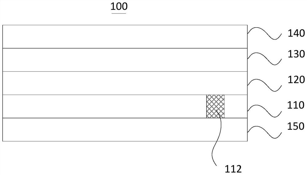
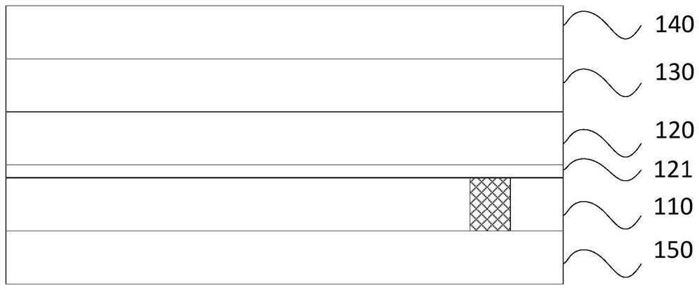
The display module, the manufacturing method of the display module and the electronic device provided by the present application relate to the field of display technology. In this application, the display module includes a polarizing structure layer, a transparent isolation layer, an adhesive layer and a cover plate structure layer. The polarizing structure layer is provided with a through hole, the through hole is filled with the first cured optical glue, and the first cured optical glue is formed by curing based on the liquid transparent optical glue. The transparent isolation layer is located on one side of the polarizing structure layer, and the projection of the transparent isolation layer on the polarizing structure layer at least covers the through hole. The cover plate structure layer is located on the side of the transparent isolation layer away from the polarizing structure layer. The adhesive layer is located between the transparent isolation layer and the cover plate structure layer. Based on the above arrangement, it is possible to improve the problem that in the prior art, the light output at the corresponding position is easily disturbed because the liquid transparent optical glue in the through-hole region and the optical glue used for laminating the cover plate are difficult to be effectively integrated, thereby causing the display effect to decrease. question.

Description

technical field [0001] The present application relates to the field of display technology, and in particular, to a display module, a manufacturing method of the display module, and an electronic device. Background technique [0002] In the under-screen camera technology, since the polarizing structure (POL) included in the display module is opaque, the polarizing structure needs to be perforated at the position corresponding to the image acquisition device (such as the front camera of an electronic device). [0003] In the prior art, before the cover plate is attached to the polarizing structure, a liquid transparent optical glue (OCR, Optical Clear Resin) is generally used to fill the opening area, and then the optical glue is used to attach the cover plate. According to the research of the inventor, based on the above arrangement in the prior art, it is easy to generate lamination bubbles, which will affect the display effect of the display module. SUMMARY OF THE INVENTI...

Claims


Application Information

Patent Timeline
Patent Type & Authority Patents(China)
IPC IPC(8): H01L27/32B32B7/12B32B17/06B32B27/06B32B27/28B32B27/32B32B27/36B32B33/00
CPCB32B27/281B32B27/36B32B27/325B32B27/06B32B17/06B32B33/00B32B7/12H10K59/00
Inventor 张探
Owner KUNSHAN NEW FLAT PANEL DISPLAY TECH CENT
Learn More