Driving guide mechanism of rail-road car

A road-rail dual-purpose vehicle and a guiding mechanism technology, which is applied to rail and road dual-purpose vehicles, motor vehicles, transportation and packaging, etc., can solve the problem that the traction capacity of the railway cannot be further improved, the source of driving force is single, and the power of the front rubber wheel is wasted. and other problems, to achieve the effect of shortening the railway braking distance, improving the traction capacity and avoiding waste.

Pending Publication Date: 2021-06-18
CHANGZHI QINGHUA MACHINERY FACTORY
View PDF0 Cites 2 Cited by
  • Summary
  • Abstract
  • Description
  • Claims
  • Application Information

AI Technical Summary

Problems solved by technology

[0003] The present invention overcomes the deficiencies in the prior art and proposes a driving and guiding mechanism for road-rail vehicles, with the purpose of solving the problems of single driving force source, inability to further improve railway traction capacity, and power waste of front rubber wheels in existing road-rail vehicles question

Method used


Image

  • Driving guide mechanism of rail-road car
  • Driving guide mechanism of rail-road car
  • Driving guide mechanism of rail-road car

Examples


Embodiment Construction

[0022] In order to make the technical problems, technical solutions and beneficial effects to be solved by the present invention clearer, the present invention will be further described in detail in conjunction with the embodiments and accompanying drawings. It should be understood that the specific embodiments described here are only used to explain the present invention. It is not intended to limit the present invention. The technical solution of the present invention will be described in detail below in conjunction with the embodiments and drawings, but the scope of protection is not limited thereto.

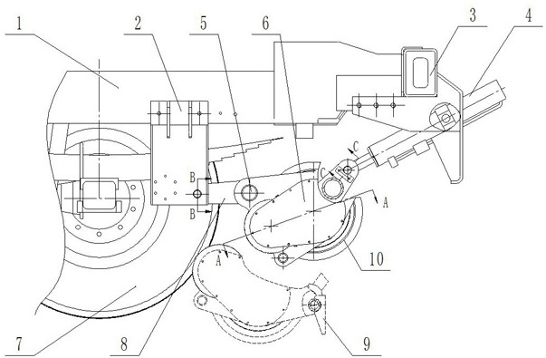
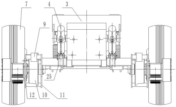
[0023] Such as Figure 1-3 As shown, the chassis longitudinal beam 1 of the road-rail vehicle is provided with a front beam 3 and a rear connecting seat 2, and the driving and guiding mechanism of the road-rail vehicle of the present invention includes a guide steel wheel 10, a rotary bracket and a guide cylinder 4 , the slewing bracket includes a connecting rod 5, a swing ro...


PUM


Abstract

The invention provides a driving guide mechanism of a road-rail car, and belongs to the technical field of road-rail cars. The problems that an existing road-rail car is single in driving force source, the railway traction capacity cannot be further improved, and power of a front rubber wheel is wasted are solved. According to the technical scheme, the mechanism comprises a guide steel wheel, a rotary support and a guide oil cylinder; one end of the guide oil cylinder is connected with the rotary support, and the other end of the guide oil cylinder is connected with a chassis of the rail-road car; the end, away from the guide oil cylinder, of the rotary support is hinged to the chassis, and a rotating shaft of the guide steel wheel is connected with the rotary support; a friction wheel is arranged on the first rotating shaft and used for being in contact with the front rubber wheel, and the first rotating shaft is connected with a rotating shaft of the guide steel wheel through a transmission device; the technical effects are as follows: the power of the front rubber wheel is reasonably utilized, the driving force source is enriched, the traction capability of a railway is improved, and the braking distance of the railway is shortened.

Description

technical field [0001] The invention belongs to the technical field of road-rail vehicles, in particular to a driving and guiding mechanism for road-rail vehicles. Background technique [0002] The existing road-rail vehicle can be divided into two types according to the driving mode, the rubber wheel drive and the steel wheel drive. The rubber wheel drive uses the drive system of the original chassis, the rear rubber wheel is used as the driving wheel, and the guide steel wheel is the passive wheel. The front rubber tire is lifted to idle. This type of public rail car is currently widely used in this field because of its low manufacturing and maintenance costs and strong power. However, the rear rubber tire is seriously worn, the load distribution is complicated, and it is easy to derail. And the power waste of the front rubber wheel, etc.; the steel wheel drive means that the rubber wheel is lifted and does not participate in the railway operation, and the guide steel whee...

Claims


Application Information

Patent Timeline
Patent Type & Authority Applications(China)
IPC IPC(8): B60F1/04
CPCB60F1/043
Inventor 马少飞韩意王爱文晋益坚曾庆华张晨崔子梓刘备咸士玉冯利平阎慧杰
Owner CHANGZHI QINGHUA MACHINERY FACTORY
Why Eureka
Try Eureka