
Pedal support with reflecting body

A technology on reflectors and brackets, applied in water conservancy projects, artificial islands, ladders, etc., can solve the problems of inconsistent pedal brackets, failure of channel marking design quality, unstable connection of pedal brackets, etc.

Inactive Publication Date: 2003-12-03
MIYAMA IND CORP
View PDF0 Cites 0 Cited by
  • Summary
  • Abstract
  • Description
  • Claims
  • Application Information

AI Technical Summary

Problems solved by technology

However, if the parts of the pedal brackets are fixed to the main body of the manhole, the water body of the river (hereinafter referred to as "the main body"), when a series of pedal brackets are installed vertically, the front and back sides of individual pedal brackets will be damaged. If there is an inversion, part of the colors will also be reversed. Therefore, the relative positions of the colors on the left and right sides of the pedal bracket are not consistent, which will lead to the failure of channel identification (ie, directional identification) and poor design quality.
Moreover, since the upper and lower parts of the reflector are joined together to form a set of reflector components, the reflector components may become unstable in connection with the pedal bracket due to long-term use.

Method used


Image

  • Pedal support with reflecting body
  • Pedal support with reflecting body
  • Pedal support with reflecting body

Examples


Embodiment Construction

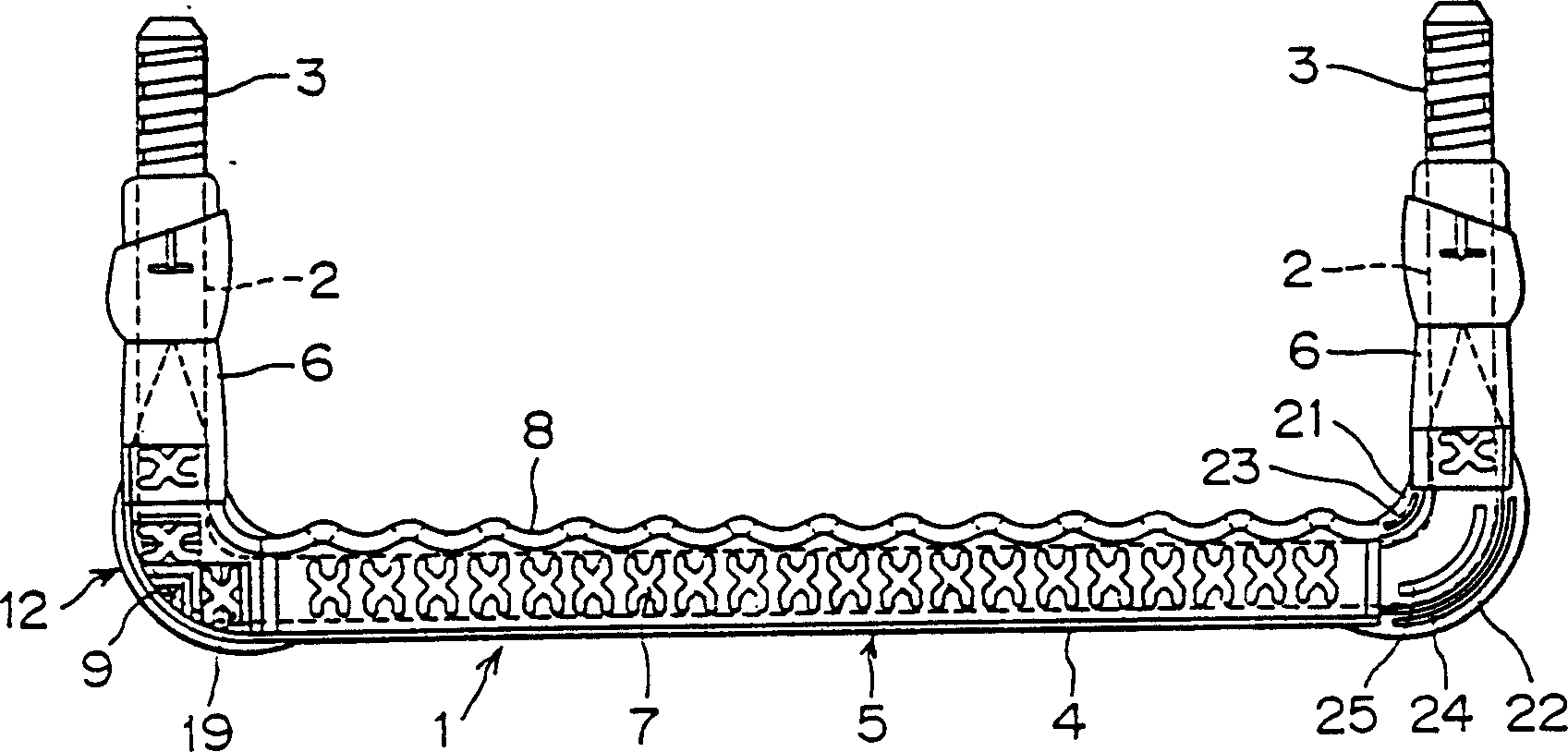
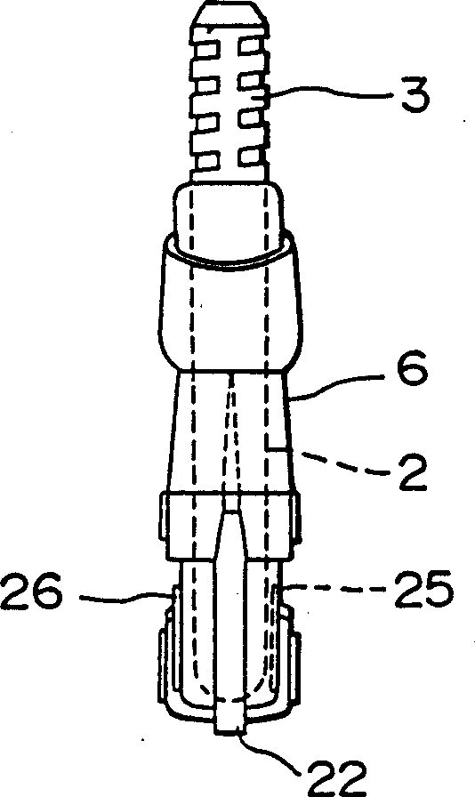
[0016] Figures 1 to 6D It is a pedal bracket equipped with a reflector according to a preferred embodiment of the present invention, wherein figure 1 is a plan view of the pedal bracket, figure 2 is the front view of the pedal bracket, image 3 is the right side view of the pedal bracket, Figure 4 Shown is the installation relationship between the reflector and the pedal bracket, and Figures 5A-5D and Figures 6A-6D It shows how the individual reflectors make up the reflector assembly.

[0017] What label 1 represents is the whole pedal support, its shape is U-shaped from the plane where it is located, including iron U-shaped inner core 2, the bending section 2A connected between two struts 3, and the package A synthetic resin outer layer 4 of a material such as polypropylene for anti-rust covering the curved section 2A and most of the outer surfaces of the struts 3 . The pedal bracket 1 is fixed on the manhole or the embankment wall, and the strut part 3 of the peda...


PUM


Abstract

A foothold provided with reflectors, which comprise a tread and side portions, wherein the foothold further comprises a set of reflector members composed of an elbow shape as viewed, a convex portion being formed on the back surface of one reflector having one color while a concave portion being formed on the back surface of another reflector having another color, a concave portion and a convex portion being formed on the foothold corresponding to the convex portion and the concave portion of each reflector, respective reflectors being retained by the foothold so as to cover the upper and lower surfaces and the front and rear surfaces of the tread and the side portions with respective reflector members at both corners formed between the tread and side portions, and the color of the upper reflector at one corner being the same as that of the lower reflector at the other corner. The foothold is easy to install and identify and which can sufficiently serve a part of as a beacon and withstand use in a long time.

Description

field of invention [0001] The invention relates to a pedal bracket with a tread part and a side end part. The pedal bracket is equipped with continuous reflectors located at both ends of the tread part. Background technique [0002] An example of a common footrest with a reflector can be found in Japanese Patent Laid-Open Publication No.9-195295, wherein the footrest has a tread part and is located at both ends of the tread part and is a continuation of the tread part. The reflectors whose planar shape is elbow shape are connected to each other in the vertical direction to form a set of reflector components. The surface and inner and outer surfaces are covered by reflector components, and the color of the reflector component at one corner is different from the color of the reflector component at the other corner. [0003] At the same time, for ordinary pedal brackets, even in a dark environment, the position of the pedaling part that people step on when going up and down ca...

Claims


Application Information

Patent Timeline
IPC IPC(8): E02D29/12E06C7/08E06C9/04
CPCE02D29/1463E06C9/04E06C7/08E02D29/12
Inventor 高桥英三
Owner MIYAMA IND CORP
Learn More