Dynamic multilayer visualization method for complex collaborative network

A collaborative network and complex technology, applied in the network field, can solve problems such as the lack of logical relationship between business services and servers, the inability of server nodes to centrally display and manage, and the difficulty of finding servers

Inactive Publication Date: 2021-06-15
广东浩云长盛网络股份有限公司
View PDF1 Cites 0 Cited by
  • Summary
  • Abstract
  • Description
  • Claims
  • Application Information

AI Technical Summary

Problems solved by technology

[0005] The purpose of the present invention is to provide a dynamic multi-layer visualization method for a complex collaborative network to solve the problem that the relationship between servers proposed in the above background technology is difficult to find changes over time, and business systems and business systems, business systems and subsystems , The problem of displaying the relationship between business systems and virtual machines, the lack of a suitable representation method for the logical relationship between business services and servers, different types of server nodes cannot be centrally displayed and managed, and the problem of quickly viewing the adjacency of server nodes

Method used


Image

  • Dynamic multilayer visualization method for complex collaborative network

Examples


Embodiment Construction

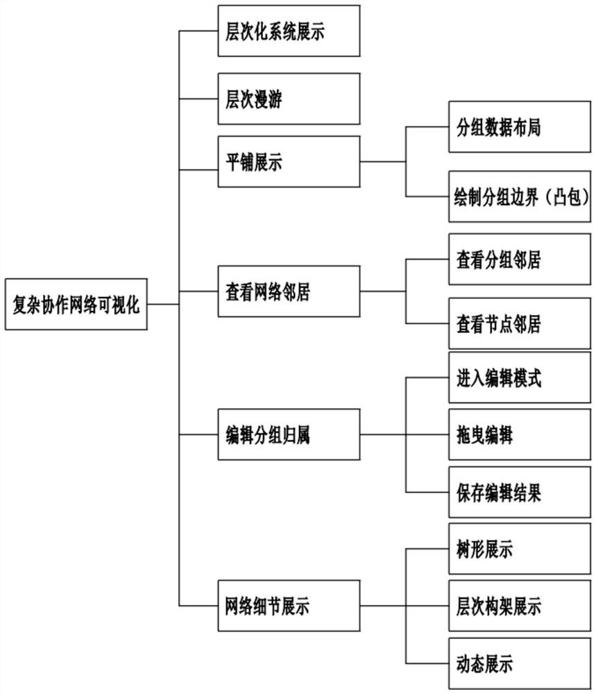
[0055] The following will be combined with figure 1 The present invention is described in detail, and the technical solutions in the embodiments of the present invention are clearly and completely described. Apparently, the described embodiments are only part of the embodiments of the present invention, not all of them. Based on the embodiments of the present invention, all other embodiments obtained by persons of ordinary skill in the art without making creative efforts belong to the protection scope of the present invention.

[0056]Unless otherwise defined, all technical and scientific terms used herein have the same meaning as commonly understood by one of ordinary skill in the technical field of the invention. The terms used herein in the description of the present invention are for the purpose of describing specific embodiments only, and are not intended to limit the present invention. As used herein, the term "and / or" includes any and all combinations of one or more of...


PUM


Abstract

The invention relates to the technical field of networks, in particular to a dynamic multilayer visualization method of a complex collaborative network. The method is characterized by comprising the following steps: S1, hierarchical system display: (1) acquiring system and network data and affiliation from a database; (2) processing the data into JSON data, and submitting the JSON data to a foreground; (3) finally drawing a structure chart according to a data format; S2, hierarchical roaming: (1) acquiring JSON data; (2) screening coarse and fine data or fine-grained data according to a user; (3) finally, drawing demand strength network data according to user demands. The method has the beneficial effects that hierarchical architecture display is converted from a traditional server architecture diagram, so that operation and maintenance personnel in a data center can conveniently check node roles in the system, and dynamic time slice display is performed according to change data of a network in the system along with time; a user can check the historical change condition of the grid nodes in the system according to the function.

Description

technical field [0001] The invention relates to the field of network technology, in particular to a dynamic multi-layer visualization method of a complex collaborative network. Background technique [0002] Complex network is a very general way of abstracting and describing complex systems. It emphasizes the topological characteristics of the system structure. The topological properties of complex networks mainly include degree and degree distribution, average path length, and clustering coefficient. [0003] Chinese Patent No. CN108446384A provides a WebGL-based network topology visualization system and data visualization method. The system includes: a large-scale network topology visualization display system, a data middle layer and a back-end server; the data middle layer is an intermediate connection part between the front-end browser and the back-end server, and is used to process data changes at the front-end and back-end; the data middle layer It is used for processi...

Claims


Application Information

Patent Timeline
Patent Type & Authority Applications(China)
IPC IPC(8): H04L12/24
CPCH04L41/044H04L41/14H04L41/22
Inventor 朱红兵
Owner 广东浩云长盛网络股份有限公司
Why Eureka
Try Eureka