Direct-current residual current protection device for split type charging and swapping equipment

A technology for charging and replacing equipment and residual current, which is applied in battery circuit devices, emergency protection circuit devices, emergency protection devices with automatic disconnection, etc., and can solve the problem of inability to achieve leakage protection action customization and ineffective current protection, etc. problem, to achieve a comprehensive effect of protection

Pending Publication Date: 2021-06-15
SGCC SMART ENERGY & ELECTRIC TRANSPORTATION TECH INNOVATION CENT (SUZHOU) CO LTD
View PDF0 Cites 0 Cited by
  • Summary
  • Abstract
  • Description
  • Claims
  • Application Information

AI Technical Summary

Problems solved by technology

Due to the high power, the general rectifier cabinet adopts a multi-channel method. When the charging module inside it adopts a non-isolated topology, if a DC leakage occurs on the DC side at this time, the leakage current will be shunted at the AC incoming line, and the charging terminal will enter The leakage current detected at the line is only half of the DC leakage current, which cannot reach the customized leakage protection action, the circuit breaker will not trip, and cannot effectively protect the current

Method used


Image

  • Direct-current residual current protection device for split type charging and swapping equipment
  • Direct-current residual current protection device for split type charging and swapping equipment
  • Direct-current residual current protection device for split type charging and swapping equipment

Examples


Embodiment

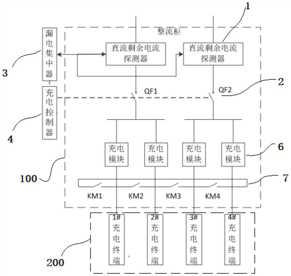
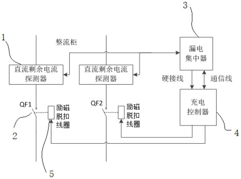
[0019] See attached Figure 1-2 As shown, a split-type DC residual current protection device for charging and replacing equipment of the present invention includes a rectifier cabinet 100 and a number of charging terminals 200 connected to the DC output end of the rectifier cabinet 100. The input end of the rectifier cabinet 100 is connected to several There are two AC incoming lines.

[0020] It also includes a DC residual current detector 1 and a molded case circuit breaker 2 corresponding to the AC incoming line. The DC residual current detector 1 is set on the AC incoming line and is used to detect the residual current of the circuit. Each DC residual current detector The output terminals of 1 are all connected to the input terminals of the leakage concentrator 3, and the leakage concentrator 3 is used for summing the residual current and comparing it with the preset value. The DC residual current detector 1 communicates with the leakage concentrator 3 through the RS485 b...


PUM


Abstract

The invention discloses a direct-current residual current protection device for split type charging and swapping equipment. The direct-current residual current protection device comprises a rectifier cabinet and a plurality of charging terminals in communication connection with the direct-current output end of the rectifier cabinet, wherein an input end of the rectifier cabinet is connected with a plurality of alternating-current inlet wires. The direct-current residual current protection device further comprises direct-current residual current detectors and molded case circuit breakers which are arranged corresponding to the alternating-current inlet wires, wherein the direct-current residual current detectors are arranged on the alternating-current inlet wires and used for detecting residual current of a loop, an output end of each direct-current residual current detector is connected with an input end of the electric leakage concentrator, the electric leakage concentrator is used for summing residual current and comparing the sum with a preset value, an output end of the electric leakage concentrator is connected with an input end of a charging controller, the molded case circuit breakers are used for controlling on-off of an alternating current inlet wire and connected with an output end of the charging controller, and a control output end of the charging controller drives the molded case circuit breakers to be switched on and off through an excitation trip coil. Leakage current can be collected before shunting, and an AC wire inlet end of the charging module is tripped off, so that the protection is more comprehensive.

Description

technical field [0001] The invention relates to the technical field of new energy vehicle charging, in particular to a DC residual current protection device for split-type charging and swapping equipment. Background technique [0002] With the popularity of new energy vehicles, how to efficiently and safely charge new energy vehicles has become a problem that needs to be improved. The split charging pile is a common equipment for charging new energy vehicles. The split charging pile is generally composed of a rectifier cabinet and a number of charging terminals. The rectifier cabinet rectifies the AC into DC, and distributes the DC to each charging terminal through power distribution. The rectifier cabinet adjusts the power distribution according to the power demanded by the charging vehicle to meet the charging demand. Due to the high power, the general rectifier cabinet adopts a multi-channel method. When the charging module inside it adopts a non-isolated topology, if a...

Claims


Application Information

Patent Timeline
Patent Type & Authority Applications(China)
IPC IPC(8): H02J7/00H02H3/33
CPCH02H3/332H02J7/0029H02J7/0031
Inventor 贾俊国于文斌朱卫东张峰宋锦海
Owner SGCC SMART ENERGY & ELECTRIC TRANSPORTATION TECH INNOVATION CENT (SUZHOU) CO LTD
Why Eureka
Try Eureka