
Method for improving Doppler tolerance of slow time phase coded signal of sky wave radar

A technology of phase encoding signal and Doppler tolerance, applied in the field of radar communication, can solve the problem of low Doppler tolerance, achieve the effect of expanding application, reducing Doppler ambiguity, and reducing target detection ambiguity

Pending Publication Date: 2021-06-15
HARBIN INST OF TECH
View PDF0 Cites 0 Cited by
  • Summary
  • Abstract
  • Description
  • Claims
  • Application Information

AI Technical Summary

Problems solved by technology

[0006] The purpose of the present invention is to solve the problem of low Doppler tolerance caused by the slow time phase encoding of the existing sky wave radar LFMCW, and propose a method for improving the Doppler tolerance of the sky wave radar slow time phase encoding signal

Method used


Image

  • Method for improving Doppler tolerance of slow time phase coded signal of sky wave radar
  • Method for improving Doppler tolerance of slow time phase coded signal of sky wave radar
  • Method for improving Doppler tolerance of slow time phase coded signal of sky wave radar

Examples


specific Embodiment approach 1

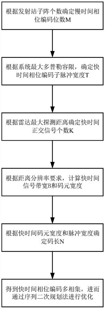
[0045] Specific implementation mode 1: In this implementation mode, a method for improving the Doppler tolerance of sky-wave radar slow-time phase encoding signal The specific process is as follows:

[0046] For sky-wave MIMO radar, use orthogonal coding to improve the Doppler tolerance of LFMCW slow-time phase-coded signals, alleviate the contradiction between the maximum unambiguous range and maximum unambiguous velocity, and use sequence quadratic programming to optimize fast-time coded signals Make it have better autocorrelation and cross-correlation properties.

[0047] Step 1: Assuming that the sky-wave MIMO radar transmitting station has M transmitting array elements, during the entire coherent accumulation time, the signals of N detection periods are coherently accumulated, and the N detection period signals constitute a set of slow time phase encoding signals, then the first The signals transmitted by the m transmitting array elements are:

[0048]

[0049] Wherei...

specific Embodiment approach 2

[0060] Specific embodiment two: the difference between this embodiment and specific embodiment one is: in the step 3, according to the maximum Doppler tolerance required by the sky-wave MIMO radar, the pulse width T of the fast time phase encoding signal is determined; the specific process is:

[0061] According to the maximum unambiguous velocity v max =±λ / 4MT, get the maximum Doppler tolerance f d The relationship with the pulse width T of the fast time phase encoding signal:

[0062]

[0063] get

[0064]

[0065] Where λ is the signal wavelength.

[0066] Other steps and parameters are the same as those in Embodiment 1.

specific Embodiment approach 3

[0067] Specific embodiment three: the difference between this embodiment and specific embodiment one or two is that in the step 4, the number of fast time quadrature signals is calculated according to the pulse width T of the fast time phase encoding signal; the specific process is:

[0068] The pulse width of the fast time phase encoding signal is T, and the maximum unambiguous detection distance of the LFMCW slow time phase encoding signal is:

[0069] R max =cT / 2

[0070] After replacing the LFMCW signal with the quadrature phase coded signal, select K mutually orthogonal signals in a fast time, so that the maximum unambiguous detection distance of the radar meets the detection requirements of the sky-wave MIMO radar;

[0071] K=2R max / cT

[0072] where c is the speed of light, and the size is 3×10 8 m / s; K represents the number of fast time quadrature signals, that is, s 1 ,s 2 ,...,s K Orthogonal to each other, as shown in Figure 2.

[0073] Other steps and param...


PUM


Abstract

The invention relates to a method for improving Doppler tolerance of slow time phase-coded signals of sky wave radar and particularly relates to a method for improving Doppler tolerance of slow time phase-coded signals of sky wave radar. The method aims to solve a problem of low Doppler tolerance caused by LFMCW (Linear Frequency Modulation Continuous Wave) slow time phase coding of the existing sky wave radar. The method comprises the following steps of 1, setting that a sky wave MIMO radar transmitting station has M transmitting array elements, detecting periodic signals to form a group of slow time phase coded signals, and setting the signal transmitted by the mth transmitting array element as sm(t); 2, determining a slow time phase code; 3, determining the pulse width of the fast time phase coded signal; 4, calculating the number of the fast time orthogonal signals; 5, calculating the code element width of the fast time phase coding signal; 6, calculating the number of code elements of fast time phase coding; 7, obtaining a phase matrix of the optimized fast time orthogonal coding multi-phase set; and 8, obtaining a final transmitting signal of the MIMO radar. The invention relates to the field of radar communication.

Description

technical field [0001] The invention relates to the field of radar communication, in particular to a method for improving the Doppler tolerance of sky-wave radar slow-time phase encoding signals. Background technique [0002] MIMO (Multiple Input Multiple Output) radar refers to any radar system that detects a target by transmitting multiple signals (that is, using waveform diversity capabilities), and uses similar multiple patterns to receive and process signals. MIMO radar adopts multi-antenna technology at both the transmitting end and the receiving end. Each transmitting array element controls the transmitting waveform of each channel and radiates mutually orthogonal signals at the same time. At the receiving end, each array element receives all transmitted signals and performs signal sorting. Such parallel multi-channel acquisition of information greatly improves the overall performance of the radar system. Compared with traditional phased array radar, MIMO radar has t...

Claims


Application Information

Patent Timeline
IPC IPC(8): G01S7/282
CPCG01S7/282
Inventor 毛兴鹏张柔耿钧
Owner HARBIN INST OF TECH
Learn More