Eureka AIR delivers breakthrough ideas for toughest innovation challenges, trusted by R&D personnel around the world.

Rotating shaft mechanism capable of rotating by 360 degrees and electronic equipment

A shaft and shaft technology, which is applied in the field of smart devices, can solve the problems of structural limitations, limited use angles of electronic devices, and the inability of two bodies to be closely attached together, so as to achieve the effect of not being easy to separate and stably closing

Active Publication Date: 2021-06-15
LENOVO (BEIJING) LTD
View PDF5 Cites 1 Cited by
  • Summary
  • Abstract
  • Description
  • Claims
  • Application Information

AI Technical Summary

Problems solved by technology

[0002] At present, many electronic devices, such as notebook computers, cannot achieve 360° rotation between the first body and the second body, resulting in limited use angles of electronic devices
And even though there are some electronic devices that can realize the cooperation between the first body and the second body to complete the 360° rotation, due to structural limitations, when the two bodies turn to 0° or 360°, the two bodies will be "rotated". "Smile", that is, the two bodies cannot be tightly attached to each other

Method used

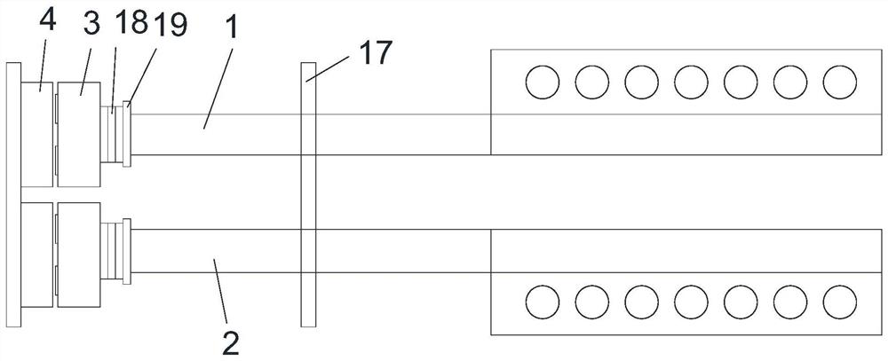
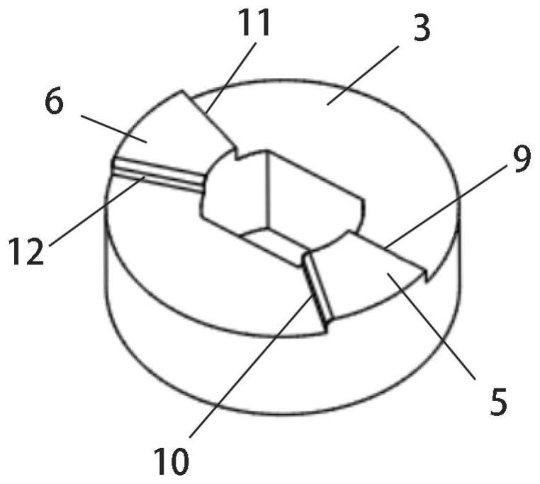
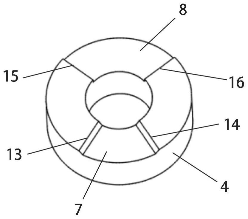

Image

  • Rotating shaft mechanism capable of rotating by 360 degrees and electronic equipment
  • Rotating shaft mechanism capable of rotating by 360 degrees and electronic equipment
  • Rotating shaft mechanism capable of rotating by 360 degrees and electronic equipment

Examples


Embodiment Construction

[0044] Below, specific embodiments of the present application will be described in detail in conjunction with the accompanying drawings, but it is not intended as a limitation of the present application.

[0045]It should be understood that various modifications may be made to the embodiments disclosed herein. Accordingly, the following description should not be viewed as limiting, but only as exemplifications of embodiments. Those skilled in the art will envision other modifications within the scope and spirit of the disclosure.

[0046] The accompanying drawings, which are incorporated in and constitute a part of this specification, illustrate embodiments of the disclosure and, together with the general description of the disclosure given above and the detailed description of the embodiments given below, serve to explain the embodiments of the disclosure. principle.

[0047] These and other characteristics of the present application will become apparent from the following ...


PUM


Abstract

The invention provides a rotating shaft mechanism capable of rotating by 360 degrees and electronic equipment. The rotating shaft mechanism comprises a first shaft body, a second shaft body, a first torsion mechanism and a second torsion mechanism, wherein the first shaft body and the second shaft body are symmetrically arranged. The first torsion mechanism and the second torsion mechanism correspond to the two shaft bodies and are the same in structure. The first torsion structure comprises a first concave wheel and a first cam which generate torsion through friction. The first concave wheel comprises a first concave pit and a second concave pit which are formed at different positions of the concave surface; the first cam comprises a first convex block and a second convex block which are arranged at different positions of the convex surface, the two concave pits and the two convex blocks are respectively provided with a first side edge, a second side edge, an outer side edge and an inner side edge, and the first side edges and the second side edges are respectively formed by a slope and linearly extend along the radius direction of a wheel body; and when the rotating shaft mechanism moves from a first angle to 0 degree, the first side edge of the first convex block is located between the first side edge and the second side edge of the first concave pit and moves towards the second side edge, and when the rotating shaft mechanism moves to 0 degree, a first specific distance exists between the first side edge of the first convex block and the second side edge of the first concave pit.

Description

technical field [0001] The embodiments of the present application relate to the field of smart devices, and in particular to a rotating shaft mechanism capable of rotating 360 degrees and an electronic device. Background technique [0002] At present, many electronic devices, such as notebook computers, cannot achieve 360° rotation between the first body and the second body, resulting in limited use angles of the electronic devices. And even though there are some electronic devices that can realize the cooperation between the first body and the second body to complete the 360° rotation, due to structural limitations, when the two bodies turn to 0° or 360°, the two bodies will be "rotated". "Smile", that is, the two bodies cannot be tightly attached to each other. Contents of the invention [0003] Embodiments of the present application provide a rotating shaft mechanism capable of realizing 360° rotation of an electronic device, and enabling two bodies of the electronic d...

Claims


Application Information

Patent Timeline
Patent Type & Authority Applications(China)
IPC IPC(8): F16C11/04F16C11/12
CPCF16C11/04F16C11/12
Inventor 元春峰尤德涛
Owner LENOVO (BEIJING) LTD
Why Eureka
Eureka Blog
Learn More