Electrode component and electrode balloon catheter
A balloon catheter and electrode technology, applied in the field of medical devices, can solve problems such as difficulty in passing through the electrode balloon catheter and breakage of components, and achieve the effect of reducing the passing size and making the passing size small.
- Summary
- Abstract
- Description
- Claims
- Application Information
AI Technical Summary
Problems solved by technology
Method used
Image
Examples
Embodiment 1
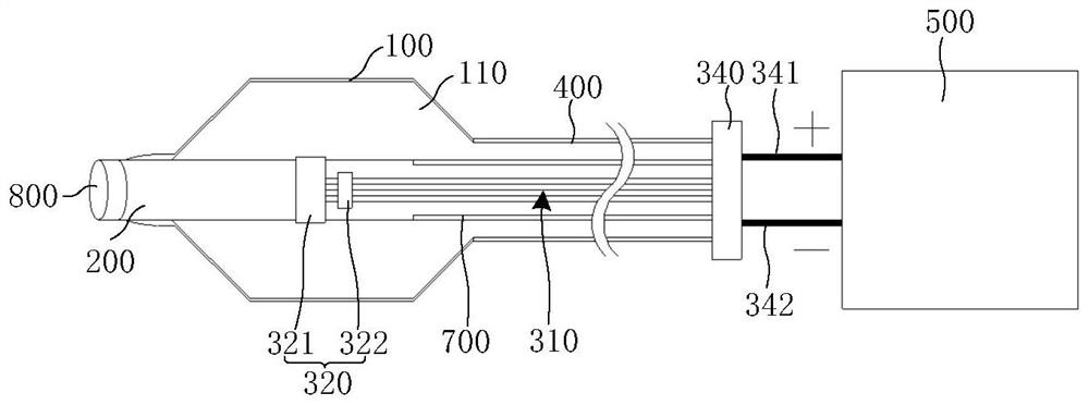
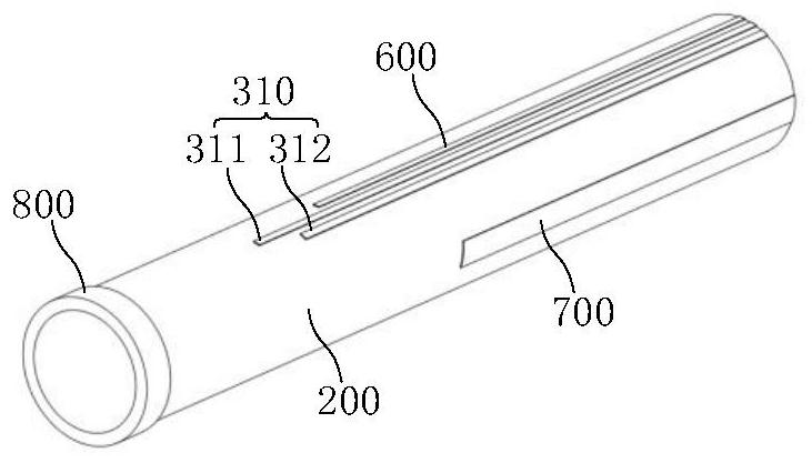
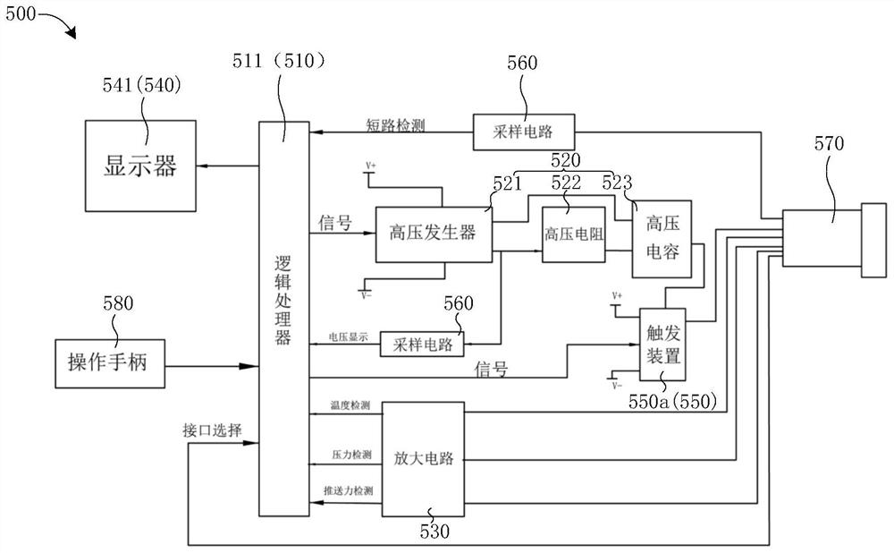
[0049] Please refer to Figure 1 to Figure 7b , figure 1 It is a schematic diagram of the electrode balloon catheter in Embodiment 1 of the present invention; figure 2 It is a schematic diagram of the inner catheter of Embodiment 1 of the present invention; image 3 It is a circuit diagram of the high-voltage generation and processing device in Embodiment 1 of the present invention; Figure 4 It is a simplified equivalent circuit diagram of the high-voltage generating unit of Embodiment 1 of the present invention; Figure 5 It is a flow chart of the electrode balloon catheter and the high-voltage generating and processing device according to Embodiment 1 of the present invention; Image 6 It is a flow chart of the safe operation of the electrode balloon catheter and the high-voltage generating and processing device in Embodiment 1 of the present invention; Figure 7a It is a schematic diagram of the electrode parts of Embodiment 1 and Embodiment 3 of the present invention...
Embodiment 2
[0102] Please refer to Figure 8a to Figure 8b , Figure 8a It is a schematic diagram of the electrode parts of Embodiment 2 and Embodiment 3 of the present invention; Figure 8b It is another schematic diagram of the electrode components of Embodiment 2 and Embodiment 3 of the present invention.
[0103] The same parts of the electrode components in the second embodiment and the first embodiment will not be described, and only the differences will be described below.
[0104] like Figure 8a and Figure 8b As shown, the insulating connector 3204 is laid on the housing structure 3203, and the second electrode 3202 is arranged on the insulating connector 3204, so that the electrode part 320 is also arranged in a single-layer structure. On the inner catheter 200, the passing size of the electrode balloon catheter is further reduced. Similarly, the discharge of the first electrode 3201 and the second electrode 3202 is same-layer discharge. Further, the housing structure 320...
Embodiment 3
[0107] Figure 7a It is a schematic diagram of the electrode components of Embodiment 1 and Embodiment 3 of the present invention. Figure 7b It is another schematic diagram of the electrode components of Embodiment 1 and Embodiment 3 of the present invention. Figure 8a It is a schematic diagram of the electrode components of Embodiment 2 and Embodiment 3 of the present invention. Figure 8b It is another schematic diagram of the electrode components of Embodiment 2 and Embodiment 3 of the present invention.
[0108] The same parts of the electrode components in the third embodiment as those in the first and second embodiments will not be described, and only the differences will be described below.
[0109] Please refer to Figure 7a to Figure 8b , the electrode part 320 provided in this embodiment is used for an electrode balloon catheter, and the electrode part 320 includes: a first electrode 3201 and a plurality of second electrodes 3202 .
[0110] The first electrode ...
PUM
 Abstract
Description
Claims
Application Information
 - R&D Engineer
- R&D Manager
- IP Professional
- Industry Leading Data Capabilities
- Powerful AI technology
- Patent DNA Extraction
Browse by: Latest US Patents, China's latest patents, Technical Efficacy Thesaurus, Application Domain, Technology Topic, Popular Technical Reports.
© 2024 PatSnap. All rights reserved.Legal|Privacy policy|Modern Slavery Act Transparency Statement|Sitemap|About US| Contact US: help@patsnap.com


