
Multi-directional drying equipment for soaked wood boards during high-end equipment manufacturing

A drying equipment, multi-directional technology, applied in the direction of humidity control wood, manufacturing tools, drying solid materials, etc.

Active Publication Date: 2021-06-08
广东国方家居有限公司
View PDF4 Cites 3 Cited by
  • Summary
  • Abstract
  • Description
  • Claims
  • Application Information

AI Technical Summary

Problems solved by technology

[0004] In order to overcome the shortcomings of the prior art that people need to manually scrape off the water on the plank and manually move and turn over the plank, the purpose of the present invention is to provide a device that can clamp the plank, automatically scrape off the water on the plank and can High-end equipment that makes wood boards evenly dried Multi-directional drying equipment for soaking wood boards during manufacturing

Method used


Image

  • Multi-directional drying equipment for soaked wood boards during high-end equipment manufacturing
  • Multi-directional drying equipment for soaked wood boards during high-end equipment manufacturing
  • Multi-directional drying equipment for soaked wood boards during high-end equipment manufacturing

Examples


Embodiment 1

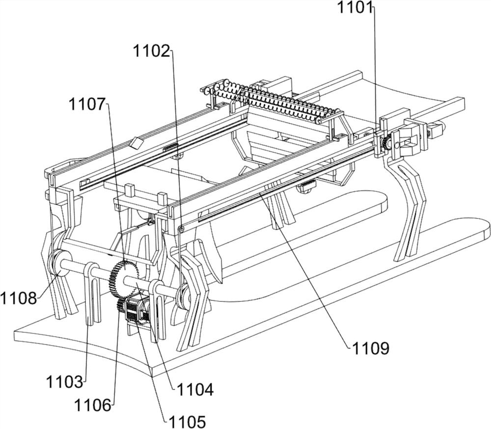
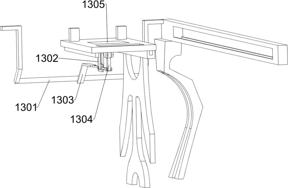
[0032] A multi-directional drying equipment for soaking wood boards during the manufacture of high-end equipment, such as figure 1 , figure 2 and image 3 As shown, it includes a bottom plate 1, a bracket 2, a chute 3, a surface dewatering mechanism 4 and a drying mechanism 5. There are brackets 2 on the four sides of the top of the bottom plate 1, and there are slides between the two brackets 2 on the same side. A surface dewatering mechanism 4 is arranged between the groove 3 and the chute 3, and a drying mechanism 5 is arranged on the chute 3.

[0033] First, people use tools to move the soaked wooden board between the surface dewatering mechanism 4, and then move the wooden board to the right, so that the surface dewatering mechanism 4 scrapes off the water on the surface of the wooden board, and then people start the drying mechanism 5 to make the drying The drying mechanism 5 dries the wooden boards moved below it, and people can take away the wooden boards after the ...

Embodiment 2

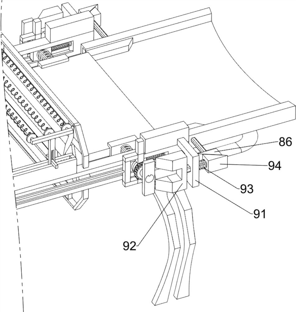
[0038] On the basis of Example 1, such as figure 1 , Figure 4 , Figure 5 , Figure 6 , Figure 7 , Figure 8 and Figure 9 As shown, it also includes a feed guide mechanism 8, and the feed guide mechanism 8 includes a second connecting rod 81, a guide plate 82, a fourth spring 83, a trapezoidal block 84, a third connecting rod 85 and a first wedge block 86, left The two brackets 2 on the side are provided with a second connecting rod 81, and a guide plate 82 is arranged between the second connecting rods 81. The front and rear sides of the guide plate 82 are symmetrically provided with a fourth spring 83, and the guide plate 82 slides symmetrically. The formula is provided with a trapezoidal block 84, the trapezoidal block 84 is connected with the fourth spring 83, the third connecting rod 85 is provided on the trapezoidal block 84, the third connecting rod 85 slides on the guide plate 82, and the end of the third connecting rod 85 Each is provided with a first wedge b...


PUM


Abstract

The invention relates to drying equipment, in particular to multi-directional drying equipment for soaked wood boards during high-end equipment manufacturing. According to the multi-directional drying equipment for the soaked wood boards during the high-end equipment manufacturing, the wood boards can be clamped, water on the wood boards can be automatically scraped off, and the wood boards can be evenly dried. The multi-directional drying equipment for the soaked wood boards during the high-end equipment manufacturing comprises a bottom plate, and supports are arranged on the four sides of the top of the bottom plate; sliding grooves arranged between the two supports on the same side; a surface water removal mechanism arranged between the sliding grooves; and drying mechanisms arranged on the sliding grooves. By arranging the surface water removal mechanism, water on the surfaces of the wood boards can be scraped off, and then wood blocks are dried under the cooperation of the drying mechanisms.

Description

technical field [0001] The invention relates to a drying device, in particular to a multi-directional drying device for soaking wooden boards during the manufacture of high-end equipment. Background technique [0002] When people manufacture high-end equipment, they need to soak the wooden boards required for manufacturing equipment, and then dry the soaked wooden boards. Cracks appear on the surface, which in turn affects the appearance of the wood, resulting in a large waste. Therefore, most people use drying equipment to dry the wood boards. Before drying, people usually need to manually scrape off the water on the wood boards. Then, when drying, it is also necessary to manually move and turn the wooden boards, so that the wooden boards can be heated evenly, and then dried evenly. [0003] Therefore, there is an urgent need to develop a high-end equipment that can clamp the plank, automatically scrape off the water on the plank and can make the plank evenly dried. Wet th...

Claims


Application Information

Patent Timeline
Patent Type & Authority Applications(China)
IPC IPC(8): F26B5/14F26B25/04F26B25/00F26B25/02B27K1/02
CPCF26B5/14F26B25/04F26B25/00F26B25/02B27K1/02Y02P70/10
Inventor 莫浪
Owner 广东国方家居有限公司
Learn More