Combined structure air film hole for cooling front edge of turbine blade
A combined structure and technology of turbine blades, applied in the direction of supporting elements of blades, engine elements, machines/engines, etc., can solve the problems of small diameter, difficult to make air film holes in rectangular structure, unsuitable blade leading edge, etc.
- Summary
- Abstract
- Description
- Claims
- Application Information
AI Technical Summary
Problems solved by technology
Method used
Image

Examples
Embodiment 1
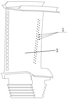
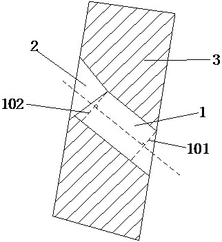
[0019] Such as figure 1 and figure 2 As shown, in order to improve the effect of air film cooling on the leading edge of the turbine rotor blade and solve the problem of air film cooling in the cylindrical air film holes on the leading edge of the blade, this embodiment provides a combined structure air film for cooling the leading edge of the turbine blade Holes, including the first through hole 1 and the tapered hole 2 connected in sequence from the inlet direction to the outlet direction, the first through hole 1 and the tapered hole 2 are combined into a combined structure air film hole, which runs through the leading edge of the turbine blade 3, wherein, The first through hole 1 is non-coaxially arranged with the tapered hole 2, which can form a better cooling air film at the leading edge of the turbine blade 3, significantly improve the cooling effect of the turbine blade 3, reduce the temperature of the wall surface of the turbine blade 3 leading edge, and The cross-s...
Embodiment 2
[0024] This embodiment is a further improvement made on the basis of Embodiment 1. The specific differences between this embodiment and Embodiment 1 are:
[0025]As a specific embodiment, it needs to be further explained in this embodiment that the taper angle of the tapered hole 2 is not less than 10°, specifically it can be 10°, 30°, 50°, 70°, 80° or 110° and so on, because the cone angle of the tapered hole 2 is less than 120°, so as long as the cone angle of the tapered hole 2 is greater than or equal to 10° and less than 120°, it can be determined according to the actual situation. Without specific limitation, the diameter of the air outlet can be increased within the same length to meet the requirement that the diameter of the air outlet of the tapered hole 2 is larger than the diameter of the first through hole 1, thereby forming a better cooling air film at the leading edge of the blade. Significantly improve the cooling effect of the blade and reduce the wall temperat...
Embodiment 3
[0027] This embodiment is a further improvement made on the basis of Embodiment 1. The specific differences between this embodiment and Embodiment 1 are:
[0028] As a specific implementation, what needs to be further explained in this implementation is that the difference from the first embodiment is that the cross section of the tapered hole 2 is an elliptical structure. The tapered hole 2 of the elliptical structure is also convenient to process, and the inner wall surface does not have any angular structure. When the cold air enters the tapered hole 2 of the elliptical structure, no additional stress will be generated, and the tapered hole 2 of the elliptical structure The end with a larger aperture is used as its gas outlet, and the end with a smaller aperture is used as its inlet. The inlet of the elliptical tapered hole 2 is connected with the outlet of the first through hole 1, ensuring gas stability. On the basis of the circulation and the enlargement of the air outle...
PUM
| Property | Measurement | Unit |
|---|---|---|
| Cone angle | aaaaa | aaaaa |
Abstract
Description
Claims
Application Information
 - R&D
- Intellectual Property
- Life Sciences
- Materials
- Tech Scout
- Unparalleled Data Quality
- Higher Quality Content
- 60% Fewer Hallucinations
Browse by: Latest US Patents, China's latest patents, Technical Efficacy Thesaurus, Application Domain, Technology Topic, Popular Technical Reports.
© 2025 PatSnap. All rights reserved.Legal|Privacy policy|Modern Slavery Act Transparency Statement|Sitemap|About US| Contact US: help@patsnap.com