Large stone carrying equipment

A technology for handling equipment and stones, which is applied in the field of large-scale stone handling equipment, and can solve the problem of low stone transfer efficiency

Inactive Publication Date: 2021-06-08
杭州富阳鼎杰石材有限公司
View PDF0 Cites 0 Cited by
  • Summary
  • Abstract
  • Description
  • Claims
  • Application Information

AI Technical Summary

Problems solved by technology

[0004] A stone mining team in a quarry is generally equipped with two fork-type loaders and one bucket loader. For large stones, two fork-type loaders are required to drag at the same time, and sometimes three fork-type loaders are required. In this case, it is necessary to borrow from the surrounding mining teams, and the remaining small stones need to wait for the loading truck to drag the large stones into place, and then come back for loading, and the transfer efficiency of the entire stone is low.

Method used


Image

  • Large stone carrying equipment
  • Large stone carrying equipment
  • Large stone carrying equipment

Examples


Embodiment Construction

[0051] The specific implementation manners of the present invention will be further described in detail below in conjunction with the accompanying drawings and embodiments. The following examples or drawings are used to illustrate the present invention, but not to limit the scope of the present invention.

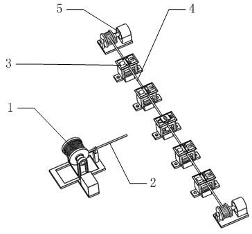
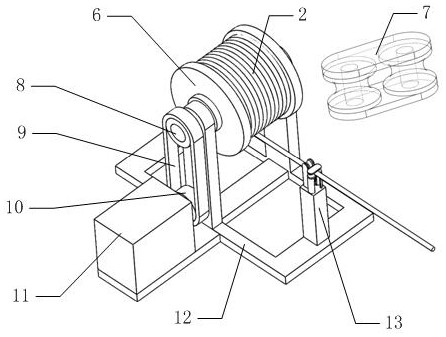
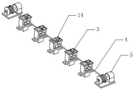
[0052] Such as figure 1 As shown, it includes a drag mechanism 1, a position adjustment mechanism 3, a position adjustment drive mechanism 5, a sliding mechanism 14, wherein as figure 2 As shown, the drag mechanism 1 is fixedly installed in the open space on the rear side of the stone block 68 stacking area in the quarry by bolts, as image 3 As shown, a plurality of position adjustment mechanisms 3 are horizontally and uniformly fixedly installed on the rear side of the stone block 68 stacking area in the quarry, and the position adjustment mechanism 3 is close to the stone block 68 stack area relative to the drag mechanism 1; Both sides of the position adjustment mecha...


PUM


Abstract

The invention belongs to the technical field of stone carrying, and particularly relates to large stone carrying equipment which comprises a dragging mechanism, a position adjusting mechanism, a position adjusting driving mechanism and a sliding mechanism. Stone is bound through one end of a dragging rope, then a first motor is controlled to work, and a first winding wheel is driven by the first motor to rotate. The dragging rope is wound and pulls the stone to move, in the moving process, the dragging rope can pass through the sliding mechanism, the stone is moved to the designated position through the guiding of the sliding mechanism, and compared with the dragging mode using two to three loading vehicles, the efficiency is higher; and moreover, the stone stacking position can be selectively treated according to specific conditions by adjusting the position of the sliding mechanism, and the utilization rate of the occupied space of the ground and the stone stacking uniformity are guaranteed.

Description

[0001] Technical field [0002] The invention belongs to the technical field of stone handling, in particular to a large stone handling equipment. Background technique [0003] In the process of mining stones in the quarry, the stones are cut into stones of uniform size and vertically placed by the cutting machine, and then the stones are pushed one by one from the upper side of the stones by engineering vehicles; In the process of being pushed, the stones will be hit by the ground when they are dumped, and they will be broken into stones of different sizes. The large stones are dragged by the loading vehicle, and the small stones are directly transported away by the loading vehicle. [0004] A stone mining team in a quarry is generally equipped with two fork-type loaders and one bucket loader. For large stones, two fork-type loaders are required to drag at the same time, and sometimes three fork-type loaders are required. In this case, it is necessary to borrow from the surr...

Claims


Application Information

Patent Timeline
IPC IPC(8): B65G35/00
CPCB65G35/00B65G2201/0223
Inventor 王雪莲华杰李少枝
Owner 杭州富阳鼎杰石材有限公司
Why Eureka
Try Eureka