
Air duct device and passenger car

A technology for air ducts and passenger cars, which is applied to vehicle components, transportation and packaging, and road transportation emission reduction, etc. It can solve the problems of driver fatigue driving and poor comfort

Active Publication Date: 2021-06-08
GREE ELECTRIC APPLIANCES INC
View PDF6 Cites 2 Cited by
  • Summary
  • Abstract
  • Description
  • Claims
  • Application Information

AI Technical Summary

Problems solved by technology

[0004] The inventors found that there are at least the following problems in the prior art: in order to quickly reduce the temperature, the driver adjusts the air deflector to blow directly, but this method is less comfortable and easily causes driver fatigue to drive

Method used


Image

  • Air duct device and passenger car
  • Air duct device and passenger car
  • Air duct device and passenger car

Examples


Embodiment Construction

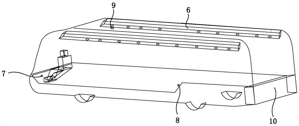
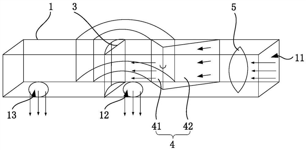
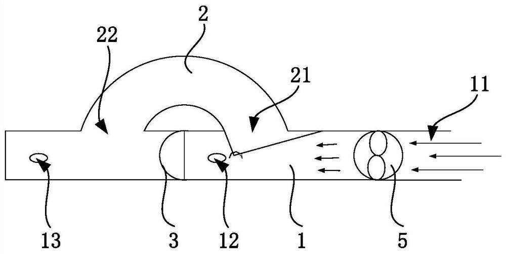
[0036] Combine below Figure 1 to Figure 5 The technical solution provided by the present invention is described in more detail.

[0037] see figure 1 with figure 2 , the embodiment of the present invention also provides an air duct device for supplying air to the driver's area of ​​passenger cars and similar vehicles. The so-called driver's area refers to the area where the driver of the bus sits, that is, the area where the steering wheel is located. The air duct device includes a first air duct 1 , a second air duct 2 , an elastic member 3 and a switch assembly 4 . The first air duct 1 and the second air duct 2 are two air ducts. The air flow enters the air duct device from the first air duct 1, then passes through the middle section of the first air duct 1 or the second air duct 2, and finally flows from the first air duct 1 to the air duct device. One or both of the first air outlet 12 and the second air outlet 13 of an air channel 1 output. In the following, the si...


PUM


Abstract

The invention discloses an air duct device and a passenger car, relates to the field of air flow regulation, and aims to realize air outlet in a vortex manner. The air duct device comprises a first air duct, a second air duct, an elastic piece and a switching assembly. The first air duct is provided with an air inlet, a first air outlet and a second air outlet. An inlet and an outlet of the second air duct communicate with the first air duct, the first communicating position of the inlet and the first air duct is located between the air inlet and the first air outlet, and the second communicating position of the outlet and the first air duct is located between the first air outlet and the second air outlet. The elastic piece is mounted in the first air channel and located between the first communication position and the second communication position. The switching assembly is mounted in the first air duct and is constructed to switch the position through air flow in the first air duct so as to block one of the first air duct and the inlet. According to the air duct device provided by the technical scheme, vortex airflow is generated, and integral bathing type air supply is formed.

Description

technical field [0001] The invention relates to the field of airflow adjustment, in particular to an air duct device and a passenger car. Background technique [0002] In the related art, the air supply outlet of the passenger car air conditioner is located at the middle and rear position on the top of the passenger car, and the air flow is transported from the air conditioner air outlet to the passenger car air duct, and then sent to the interior of the compartment by the outlet of the passenger car air duct. Along the length direction of the passenger car air duct, the passenger car air duct is provided with multiple outlets to correspond to different seats. [0003] The driver's seat of the bus has a large front windshield and side windows. Affected by the angle of solar radiation, the driver's position is exposed to direct sunlight. Under the cooling state, the temperature of the driver's position is higher, which can be more than 5°C higher than that of the middle and ...

Claims


Application Information

Patent Timeline
IPC IPC(8): B60H1/26B60H1/34
CPCB60H1/26B60H1/3457Y02T10/88
Inventor 李珂陈付齐
Owner GREE ELECTRIC APPLIANCES INC
Learn More