Heat dissipation motor

A motor body and arc-shaped technology, which is applied in the field of heat dissipation motors, can solve the problems of large motor damage, large motor vibration, and low heat dissipation efficiency, and achieve energy saving, small vibration damage, and safe and reliable use.

Active Publication Date: 2021-06-04
奥越电机有限公司
View PDF6 Cites 3 Cited by
  • Summary
  • Abstract
  • Description
  • Claims
  • Application Information

AI Technical Summary

Problems solved by technology

[0005] Aiming at the deficiencies of the prior art, the present invention provides a heat-dissipating motor, which solves the problem that the base of the motor currently used is usually fixed, the vibration generated by the motor is relatively large during use, and the damage to the motor is relatively large, and the existing motor only passes through The heat dissipation fins on the outside exchange heat with the surrounding air for heat dissipation, and the heat dissipation efficiency is low

Method used


Image

  • Heat dissipation motor
  • Heat dissipation motor
  • Heat dissipation motor

Examples


Embodiment 1

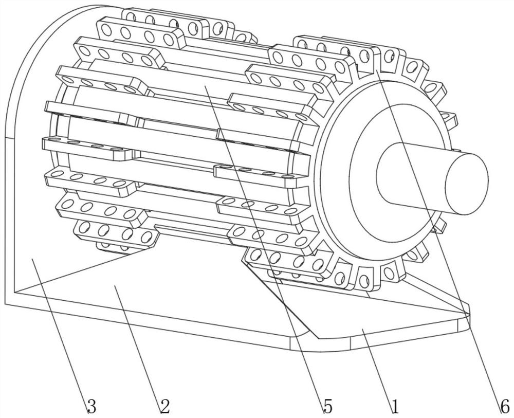
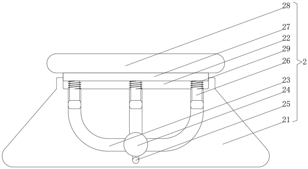
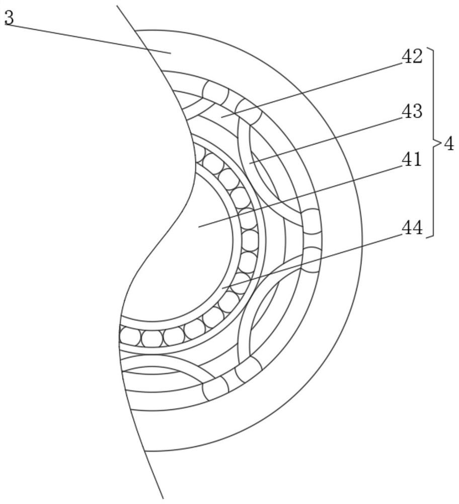
[0034] see Figure 1-3, the present invention provides a technical solution: a heat dissipation motor, including a base 1, a buffer device 2 is fixedly connected to both sides of the top of the base 1, a positioning plate 3 is fixedly connected to one end of the base 1, and the center position of one side of the positioning plate 3 is set There is a positioning device 4, the top of the buffer device 3 is fixedly connected to the motor body 5, and one end of the motor body 5 is provided with a cooling device 6, the buffer device 2 includes a support plate 21, the top of the support plate 21 is provided with a buffer groove 22, and the bottom of the inner wall of the buffer groove 22 is opened There is an air passage 23, the end of the air passage 23 away from the buffer tank 22 is connected with an air chamber 24, the bottom of the air chamber 24 is connected with an air outlet 25, the inner wall of the air passage 23 is slidingly connected with a piston rod 26, and one end of t...

Embodiment 2

[0037] see Figure 1-5 , on the basis of Embodiment 1, the present invention provides a technical solution: the cooling device 6 includes a control cavity 61, the center of the inner wall of the control cavity 61 is fixedly connected with a control seat 62, and the top of the control seat 62 is provided with a vibration groove 63. The bottom of the slot 63 is rotatably connected with a spring piece 64, and the top of the spring piece 64 is rotatably connected with a push rod 65. The top side of the push rod 65 is provided with an arc-shaped slide hole 66, and the inner wall of the arc-shaped slide hole 66 is slidably connected with a slide bar 67. One end is fixedly connected with an arc-shaped pressing rod 68, and the central position of the arc-shaped pressing rod 68 is rotationally connected with the inner wall of the control cavity 61 through a rotating bolt 69. The end of the arc-shaped pressing rod 68 away from the slide bar 67 is fixedly connected with a pressure head 61...


PUM


Abstract

The invention discloses a heat dissipation motor which comprises a base, buffer devices are fixedly connected to the two sides of the top of the base, a positioning plate is fixedly connected to one end of the base, a positioning device is arranged in the center of one side of the positioning plate, a motor body is fixedly connected to the tops of the buffer devices, and a heat dissipation device is arranged at one end of the motor body. Each buffer device comprises a supporting plate, a buffering groove is formed in the top of the supporting plate, an air channel is formed in the bottom of the inner wall of the buffering groove, the end, away from the buffering groove, of the air channel communicates with an air cavity, the bottom of the air cavity communicates with an air outlet hole, and the inner wall of the air channel is slidably connected with a piston rod. The invention relates to the technical field of motors. The heat dissipation motor is good in buffering effect, can effectively reduce vibration damage of the motor, can prevent the motor body from inclining and deviating, is safe and reliable to use, facilitates the acceleration of the flow speed of air around the cooling fins, and is good in heat dissipation effect.

Description

technical field [0001] The invention relates to the technical field of motors, in particular to a heat dissipation motor. Background technique [0002] The stator windings of ordinary asynchronous motors are connected to the AC grid, and the rotor windings do not need to be connected to other power sources. Therefore, it has the advantages of simple structure, convenient manufacture, use and maintenance, reliable operation, small mass and low cost. [0003] The motor base currently used is usually fixed, and the vibration generated by the motor is relatively large during use, causing great damage to the motor. In addition, the existing motor only dissipates heat through heat exchange with the surrounding air through the heat dissipation fins on the outside, and the heat dissipation efficiency is low. Contents of the invention [0004] (1) Solved technical problems [0005] Aiming at the deficiencies of the prior art, the present invention provides a heat-dissipating moto...

Claims


Application Information

Patent Timeline
Patent Type & Authority Applications(China)
IPC IPC(8): H02K5/00H02K5/24H02K5/18H02K9/22
CPCH02K5/00H02K5/24H02K5/18H02K9/22
Inventor 不公告发明人
Owner 奥越电机有限公司
Why Eureka
Try Eureka