
Computer mainframe heat dissipation structure

A heat dissipation structure and computer technology, applied in the computer field, can solve the problems of inconvenient quick installation or disassembly of cooling fans and thermal fins, and inability to choose a heat dissipation method.

Inactive Publication Date: 2021-06-04
SHENZHEN QIANHAIQIHAO NETWORK TECH CO LTD
View PDF0 Cites 1 Cited by
  • Summary
  • Abstract
  • Description
  • Claims
  • Application Information

AI Technical Summary

Problems solved by technology

[0002] Computer, commonly known as computer, is a modern electronic computing machine used for high-speed computing. It can perform numerical calculations, logic calculations, and storage and memory functions. It is a modern intelligent electronic device that can run according to programs and process massive amounts of data automatically and at high speed. Equipment, a general desktop computer is composed of a display screen and a host computer. Since the electronic devices in the host computer will generate a large amount of heat during operation, it is necessary to dissipate heat from the host computer. However, the existing heat dissipation structure generally uses a cooling fan to blow the CPU, etc. To cool down electronic devices, different heat dissipation methods cannot be selected at different temperatures, and the cooling fan and heat conduction sheet that dissipate heat from the CPU need to be cleaned regularly. Since the cooling fan and heat conduction sheet that dissipate heat from the CPU are currently fixed by bolts, the heat dissipation It is inconvenient to quickly install or remove the fan and heat sink

Method used


Image

  • Computer mainframe heat dissipation structure
  • Computer mainframe heat dissipation structure
  • Computer mainframe heat dissipation structure

Examples


Embodiment Construction

[0031] The following will clearly and completely describe the technical solutions in the embodiments of the present invention with reference to the accompanying drawings in the embodiments of the present invention. Obviously, the described embodiments are only part of the embodiments of the present invention, not all of them. In the case of no conflict, the embodiments in the present application and the features in the embodiments can be combined with each other. Based on the embodiments of the present invention, all other embodiments obtained by persons of ordinary skill in the art without creative efforts fall within the protection scope of the present invention.

[0032] It should be noted that if there is a directional indication (such as up, down, left, right, front, back...) in the embodiment of the present invention, the directional indication is only used to explain the position in a certain posture (as shown in the accompanying drawing). If the specific posture change...


PUM


Abstract

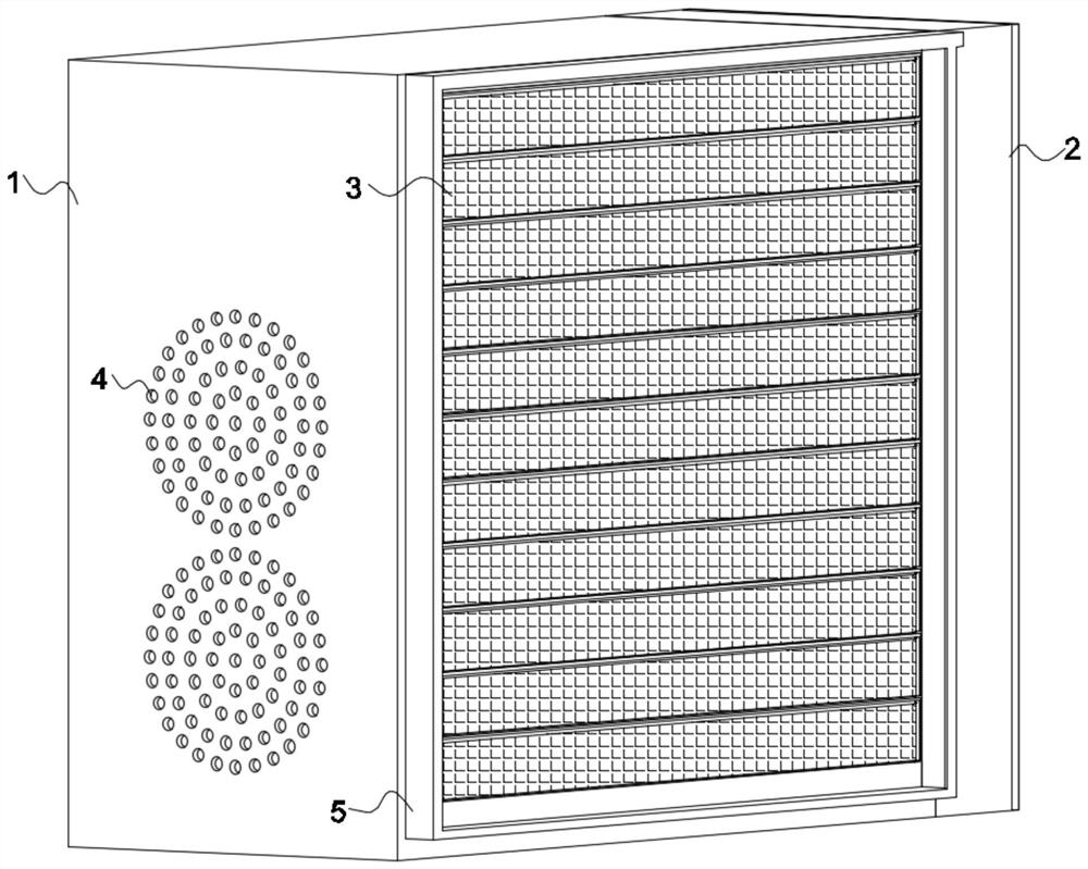
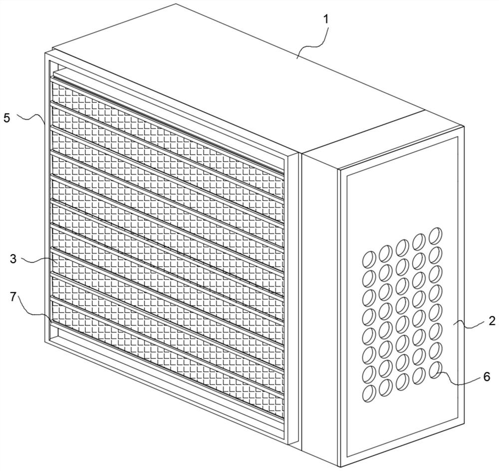
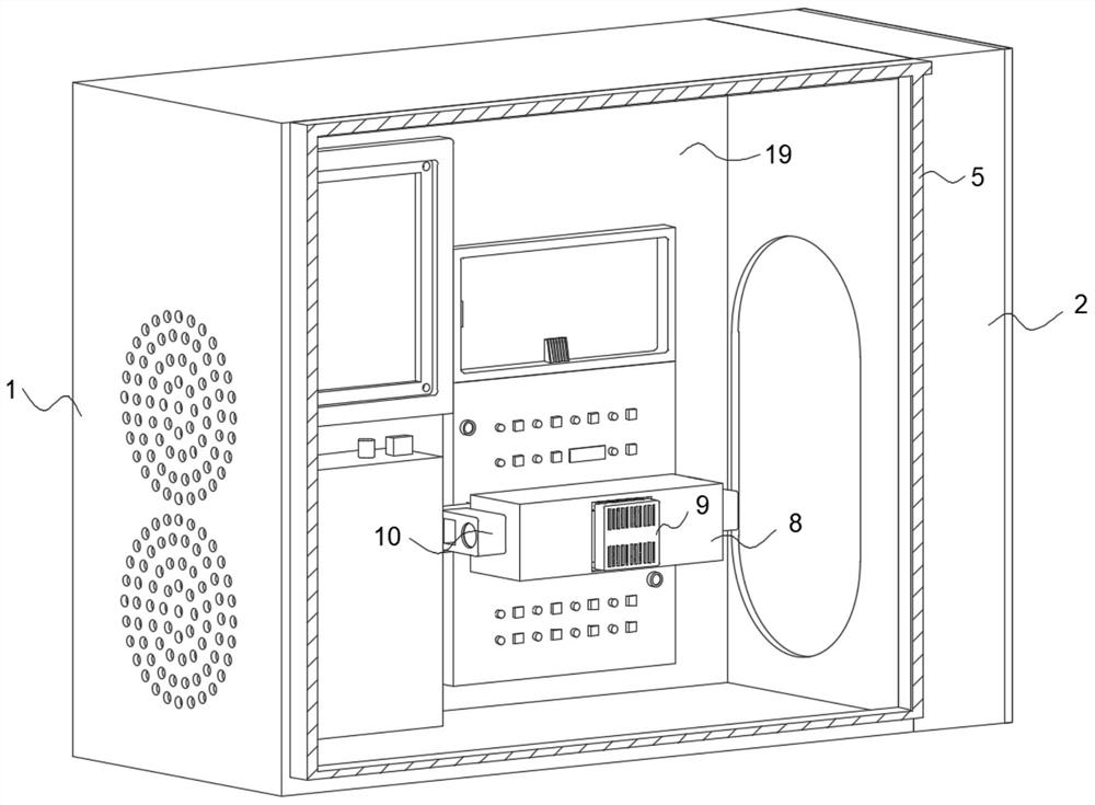
The invention discloses a computer mainframe heat dissipation structure which comprises a mainframe box, a ventilation mechanism is arranged on the mainframe box and comprises a connecting frame, a louver and a plurality of filter screens are arranged on the connecting frame, and the louver controls opening and closing through an electric telescopic rod. According to the invention, the electric telescopic rod can drive the shutter sheets at the bottom to rotate and open, when the shutter sheets at the bottom rotate, the adjacent shutter sheets can be driven to rotate in the same direction by pulling the adjacent shutters through the filter screen, and so on, so that the electric telescopic rod forms a linkage structure through the connection mode of the filter screen and the shutters; and the blind window can be conveniently and automatically opened, the filter screen can play a dustproof role on the mainframe box while the blind window is opened, the blind window can be automatically closed through the second torsion spring, the filter screen is installed on the blind window, the installation space is greatly saved, and heat on a CPU and other electronic devices is absorbed through the heat conduction plate.

Description

technical field [0001] The invention relates to the technical field of computers, in particular to a heat dissipation structure of a computer host. Background technique [0002] Computer, commonly known as computer, is a modern electronic computing machine used for high-speed computing. It can perform numerical calculations, logic calculations, and storage and memory functions. It is a modern intelligent electronic device that can run according to programs and process massive amounts of data automatically and at high speed. Equipment, a general desktop computer is composed of a display screen and a host computer. Since the electronic devices in the host computer will generate a large amount of heat during operation, it is necessary to dissipate heat from the host computer. However, the existing heat dissipation structure generally uses a cooling fan to blow the CPU, etc. To cool down the electronic components, it is impossible to choose different heat dissipation methods at ...

Claims


Application Information

Patent Timeline
IPC IPC(8): G06F1/20G06F1/18
CPCG06F1/181G06F1/20
Inventor 罗荔枝聂群卢思达谢真
Owner SHENZHEN QIANHAIQIHAO NETWORK TECH CO LTD
Learn More