
Bidirectional engagement and disengagement type ball screw inerter

A ball screw, one-way clutch technology, used in one-way clutches, clutches, springs/shock absorbers, etc.

Inactive Publication Date: 2021-06-04
NAT UNIV OF DEFENSE TECH
View PDF7 Cites 1 Cited by
  • Summary
  • Abstract
  • Description
  • Claims
  • Application Information

AI Technical Summary

Problems solved by technology

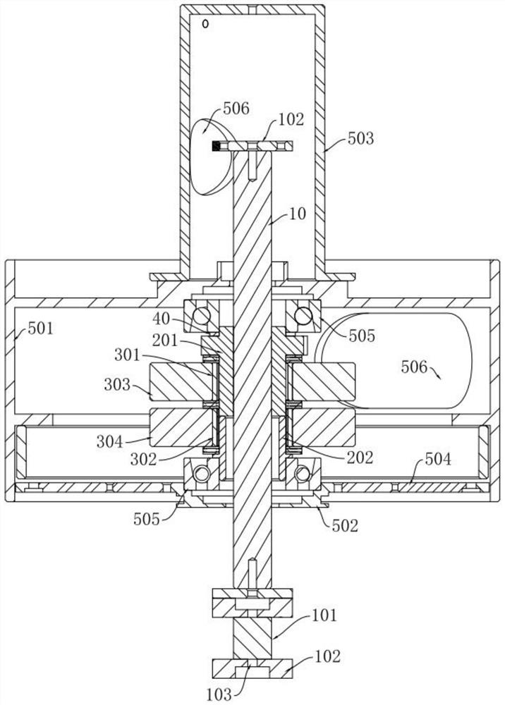
[0004] Aiming at the above-mentioned problem in the prior art that the impact caused by the inertial capacity of the general ball screw changing the rotation direction of the flywheel affects the smoothness of the inertial capacity of the ball screw, the present invention provides a two-way clutch type ball screw inerter, which ensures that the ball screw The inertia coefficient of the screw inertial movement direction is unchanged; and each flywheel does not need to change the rotation direction, thereby reducing the impact of the ball screw inertial capacity caused by the replacement of the flywheel rotation direction

Method used


Image

  • Bidirectional engagement and disengagement type ball screw inerter
  • Bidirectional engagement and disengagement type ball screw inerter
  • Bidirectional engagement and disengagement type ball screw inerter

Examples


Embodiment Construction

[0036] The technical solutions in the embodiments of the present invention will be clearly and completely described below with reference to the accompanying drawings in the embodiments of the present invention. Obviously, the described embodiments are only a part of the embodiments of the present invention, not all of the embodiments. Based on the embodiments of the present invention, all other embodiments obtained by those of ordinary skill in the art without creative efforts shall fall within the protection scope of the present invention.

[0037] It should be noted that all directional indications (such as up, down, left, right, front, back...) in the embodiments of the present invention are only used to explain the relationship between the components in a certain posture (as shown in the accompanying drawings). Relative positional relationship, movement conditions, etc., if the specific posture changes, the directional indication will also change accordingly.

[0038] In a...


PUM


Abstract

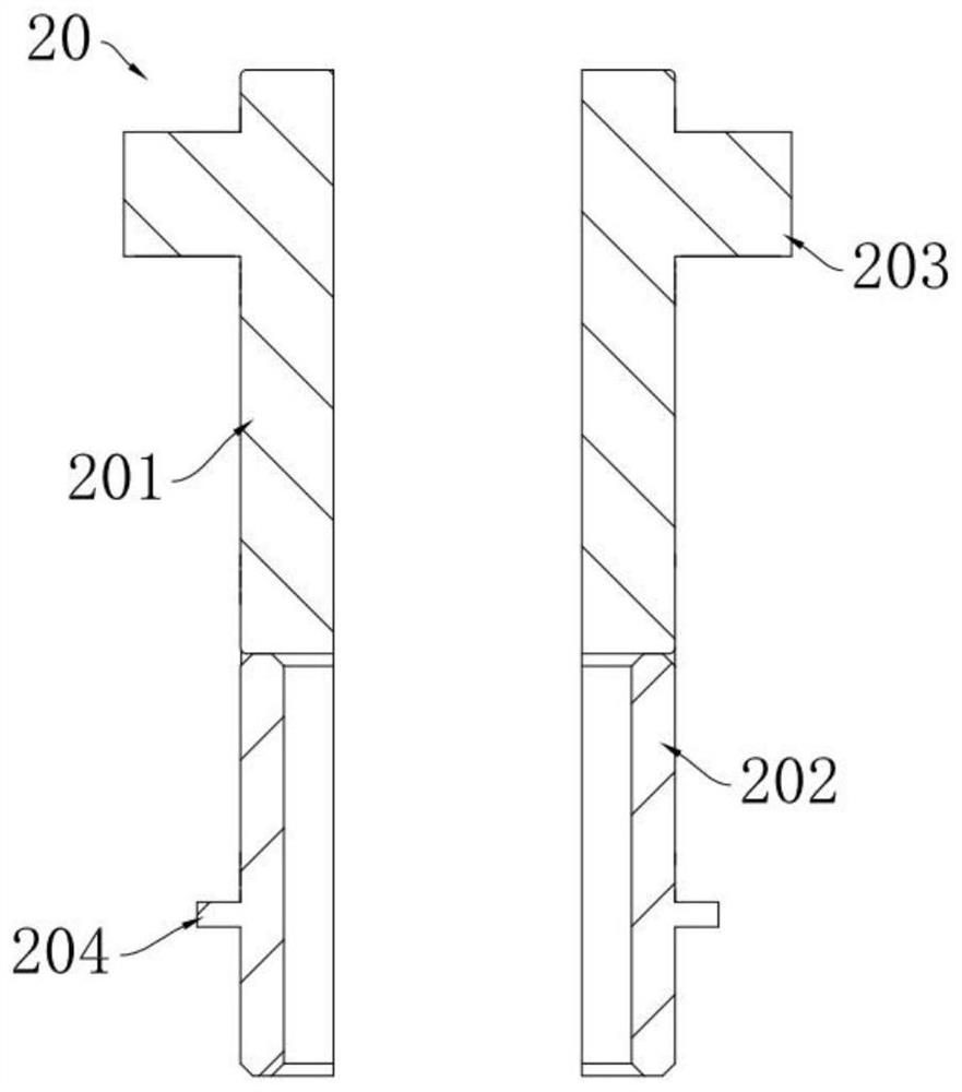
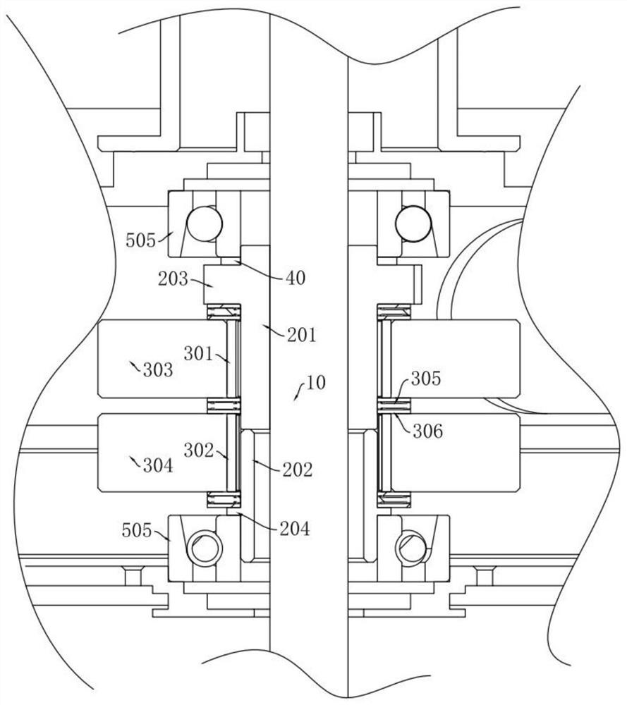
The invention discloses a bidirectional engagement and disengagement type ball screw inerter. The bidirectional engagement and disengagement type ball screw inerter comprises a base frame assembly, a screw nut assembly and a ball screw matched with the screw nut assembly; a first one-way clutch and a second one-way clutch are arranged on the screw nut assembly, and the rotation directions of the first one-way clutch and the second one-way clutch are opposite; and a first flywheel is fixedly connected to the first one-way clutch, a second flywheel is fixedly connected to the second one-way clutch, and a force transmission connecting piece is arranged on the ball screw and used for converting external vibration energy in the vertical direction into rotational inertia of the first flywheel and the second flywheel. The translation direction of the ball screw is changed under the condition that the rotation directions of the flywheels are not changed, impact caused by the change of the rotation directions of the flywheels when the movement direction of the ball screw inerter is switched is reduced, the structure is compact, the increased occupied space and the needed rotational inertia can be designed according to the use condition, and the inerter is easy to manufacture and assemble, low in manufacturing cost and has good engineering application value.

Description

technical field [0001] The invention relates to the technical field of flywheel type inerter vibration reduction, in particular to a two-way clutch type ball screw inerter, specifically a ball screw with two one-way clutches, which realizes the unidirectional rotation of the two flywheels. Screw type inerter. Background technique [0002] In 2001, Smith of Cambridge University invented the "inerter". This new type of mechanical element can provide a very large inertia with a small structural mass. An ideal inerter element is defined as a single-channel mechanical element with two relatively independent and free-moving endpoints. The forces on the two endpoints are equal in magnitude and opposite in direction, and are proportional to the relative acceleration. According to the structural principles, inerters are divided into four categories: mechanical, hydraulic, electromechanical and electromagnetic. In addition, according to the relative relationship of the transmission...

Claims


Application Information

Patent Timeline
IPC IPC(8): F16F15/31F16F15/315F16D41/066
CPCF16D41/066F16F15/31F16F15/315
Inventor 程哲李月昊胡茑庆肖卓尹正阳陈家庚王博政周洋
Owner NAT UNIV OF DEFENSE TECH
Learn More