Vehicle and locking control system
A vehicle and locking device technology, which is applied in the vehicle field and can solve problems such as the mismatch between the action mode and the state of the locking device
- Summary
- Abstract
- Description
- Claims
- Application Information
AI Technical Summary
Problems solved by technology
Method used
Image
Examples
Deformed example 1
[0104] In the embodiment, an example in which external charging is AC charging has been described. However, the external charging is not limited to AC charging, and may be DC charging that charges the vehicle-mounted battery 100 using electric power supplied from a DC power supply outside the vehicle 1 . The present disclosure can also be applied to DC charging in the same manner as AC charging.
Deformed example 2
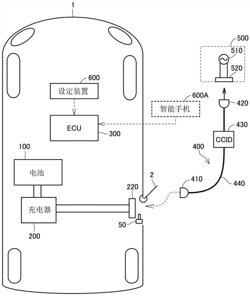
[0106] In the embodiment, an example in which setting device 600 is provided in vehicle 1 has been described. However, the setting device 600 is not limited to a device provided in the vehicle 1 . For example, the setting device 600 may include a device provided outside the vehicle 1 in addition to or instead of a device provided in the vehicle 1 . In Modification 2, the charging system also includes the user's smartphone 600A as the setting device 600 (refer to figure 1 ) example to illustrate.
[0107] Smartphone 600A is configured to be capable of wireless two-way communication with ECU 300 . Predetermined application software is installed on the smartphone 600A. Smartphone 600A is configured such that, for example, the setting of the operation mode of locking device 50 can be changed by operating a screen displayed during activation of the application software. For example, when the user operates smartphone 600A to select the first mode, smartphone 600A outputs a signa...
Deformed example 3
[0110] In the embodiment, an example in which the locking device 50 is provided in the vehicle 1 has been described. However, the function of the locking device 50 is not limited to being provided on the vehicle 1 side. For example, the function of the locking device 50 may be provided on the charging cable 400 side. In Modification 3, an example in which the function of the locking device 50 is provided on the charging cable 400 side will be described.
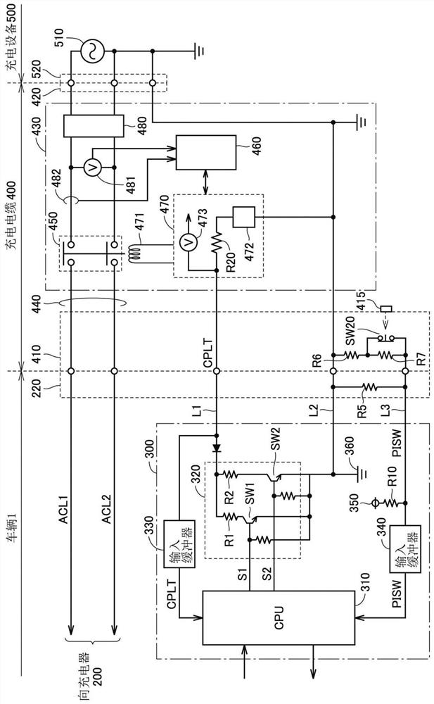
[0111] In Modification 3, push button 415 provided on charging connector 410 functions as a locking device. Specifically, the push button 415 is configured to switch between a locked state and an unlocked state. In the locked state, the push button 415 is fixed by, for example, an unillustrated actuator so as not to move even if the user presses it. In the unlocked state, the push button 415 is not fixed.
PUM
 Abstract
Description
Claims
Application Information
 - R&D
- Intellectual Property
- Life Sciences
- Materials
- Tech Scout
- Unparalleled Data Quality
- Higher Quality Content
- 60% Fewer Hallucinations
Browse by: Latest US Patents, China's latest patents, Technical Efficacy Thesaurus, Application Domain, Technology Topic, Popular Technical Reports.
© 2025 PatSnap. All rights reserved.Legal|Privacy policy|Modern Slavery Act Transparency Statement|Sitemap|About US| Contact US: help@patsnap.com


