
One-key start-stop and interlock protection control method for jet pump of condenser vacuum system

A vacuum system and interlock protection technology, which is applied to steam/steam condensers, lighting and heating equipment, etc., can solve the lack of automatic control methods and interlock protection of software, affecting the stability of the vacuum system of large machines, and auxiliary steam pressure disturbances, etc. problem, to achieve the effect of simplifying operation, ensuring safety and ensuring safety

Active Publication Date: 2021-06-01
江苏南通发电有限公司
View PDF7 Cites 0 Cited by
  • Summary
  • Abstract
  • Description
  • Claims
  • Application Information

AI Technical Summary

Problems solved by technology

However, the new steam injection system only has two first-stage injection pumps connected to the main pipe, sharing a set of terminal heat exchangers, and there is no redundant equipment. For a technology that has not yet been applied on a large scale in the power industry, there is a big problem risk
Secondly, since the steam injection system is divided into multi-stage vacuum injection pumps and heat exchangers, and the power source is auxiliary steam, it is easy to disturb the pressure of auxiliary steam. And the intake valve, the operation is cumbersome, and it will easily affect the stability of the vacuum system of the large machine
[0004] The main reasons for the above defects can be summarized into two points, one is that the vacuum ejection system does not have a redundant vacuum ejection pump on the hardware, and the other is that the software lacks automatic control methods and interlock protection

Method used


Image

  • One-key start-stop and interlock protection control method for jet pump of condenser vacuum system
  • One-key start-stop and interlock protection control method for jet pump of condenser vacuum system
  • One-key start-stop and interlock protection control method for jet pump of condenser vacuum system

Examples


Embodiment Construction

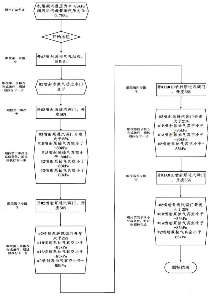
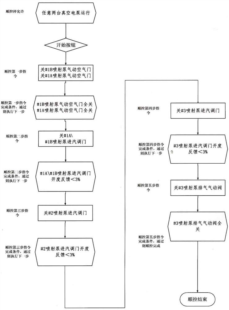
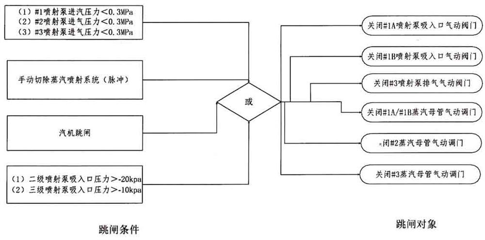
[0052] A one-button start-stop and interlock protection control method for a jet pump in a condenser vacuum system, the condenser vacuum system includes an electric pump part and a steam injection part, the electric pump part has three electric pumps, and the steam injection part is equipped with two One first-stage jet pump A, B, one second-stage jet pump, one third-stage jet pump, first-stage heat exchanger, second-stage heat exchanger, and third-stage heat exchanger; the power steam source of the four jet pumps is The auxiliary steam main pipe, the suction ports of the primary jet pumps A and B and the suction ports of the three electric pumps are all connected to the vacuum main pipe of the condenser. After the first-stage heat exchanger is cooled by condensate, it is sucked by the second-stage jet pump and discharged to the second-stage heat exchanger. After cooling again, it is sucked by the third-stage jet pump and discharged to the third-stage heat exchanger, and finall...


PUM


Abstract

The invention discloses a one-key start-stop and interlock protection control method for a jet pump of a condenser vacuum system. The condenser vacuum system comprises an electric pump part and a steam jet part, and the electric pump part is provided with three electric pumps; the steam injection part is provided with two first-stage jet pumps A and B, a second-stage jet pump, a third-stage jet pump, a first-stage heat exchanger, a second-stage heat exchanger and a third-stage heat exchanger; and power steam sources of the four jet pumps are auxiliary steam mother pipes, suction inlets of the first-stage jet pumps A and B and suction inlets of the three electric pumps are all connected to a condenser vacuum mother pipe, power steam generated after the jet pumps do work is discharged into the first-stage heat exchanger, and the steam is sucked and discharged to the second-stage heat exchanger through the second-stage jet pump after being cooled by condensed water in the first-stage heat exchanger, and after being cooled again, the steam is sucked and discharged to the third-stage heat exchanger by the third-stage jet pump and finally drained to a condensed water hot well. The method is convenient to operate and good in effect.

Description

technical field [0001] The invention relates to a one-button start-stop and interlock protection control method of a jet pump in a vacuum system of a condenser. Background technique [0002] At present, the energy-saving technical reform of coal-fired thermal power generating units is basically concentrated on two levels: the transformation of the main body of the machine and the furnace, and the transformation of the frequency conversion of the turning machine. Jiangsu Nantong Power Plant is trying to measure the problem from the level of the cold end system. In the case of the original centrifugal vacuum pump vacuuming, in A steam jet pump is installed at the vacuum main pipe of the condenser. Since the power source of the steam jet pump is high-pressure steam, it can effectively reduce the power consumption rate of the factory. [0003] However, the safety of the production process of the power plant should be higher than the economy. The original three independent elect...

Claims


Application Information

Patent Timeline
Patent Type & Authority Applications(China)
IPC IPC(8): F28B9/10F28B11/00
CPCF28B9/10F28B11/00
Inventor 张希萌谢峰陈石秦秋艳张静秋
Owner 江苏南通发电有限公司
Learn More