A cup holder structure
A cup holder and drawer technology, which is applied to special positions of vehicles, vehicle parts, transportation and packaging, etc., can solve the problems of poor use feeling, flying out of the cup holder pop-up module, inconvenient operation of beverage cups, etc., to improve safety performance, The structure is simple and the effect of improving the convenience of use
- Summary
- Abstract
- Description
- Claims
- Application Information
AI Technical Summary
Problems solved by technology
Method used
Image

Examples
Embodiment 1
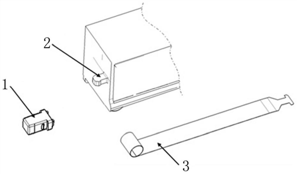
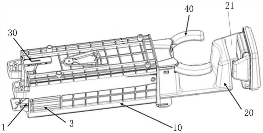
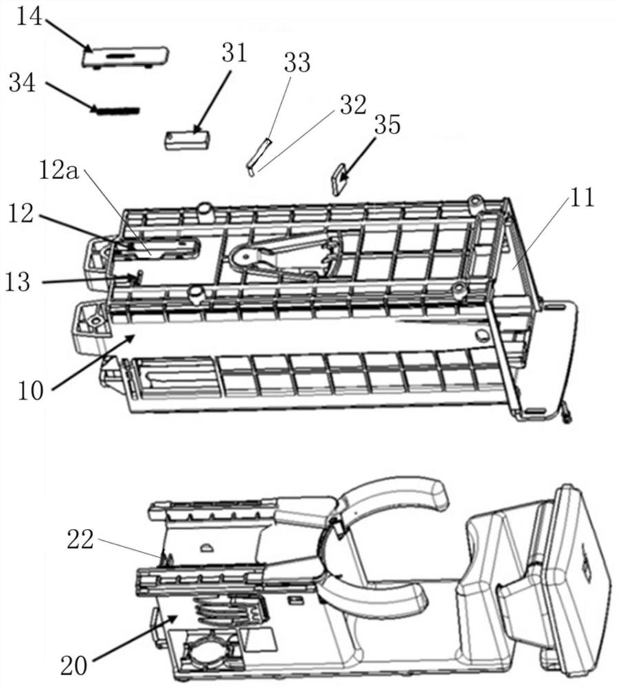
[0053] Such as Figure 2-5 As shown, the cup holder structure provided by this embodiment includes: a body 10 , a drawer 20 and an inertial self-locking structure 30 . The main body 10 is a shell structure, and an accommodating chamber 11 is arranged inside, and the drawer 20 is provided on the main body 10 so as to be able to extend out and retract into the accommodating chamber 11 . A claw mechanism 40 for fixing the cup body is provided on the part of the drawer 20 protruding from the accommodating cavity 11 , and the drawer 20 is provided with a support plate for supporting the cup body below the claw mechanism 40 .
[0054] The inertial self-locking structure 30 includes a gravity block 31 and a latch 32; the gravity block 31 is slidably arranged on the body 10 along the extension and retraction direction of the drawer 20; the latch 32 is slidably arranged on the On the body 10; the drawer 20 is provided with a locking slot 22; the gravity block 31 and the bayonet pin 32...
Embodiment 2
[0064] This embodiment is basically the same as Embodiment 1, the difference is:
[0065] Such as Figure 8-9 As shown, the jaw mechanism 40 on the drawer 20 of the present embodiment is a linkage jaw mechanism, and the linkage jaw mechanism includes a left jaw 41 and a right jaw 42 that are oppositely arranged on the left and right; The middle part is pivotally connected to the drawer 20 through the third pivot shaft 44 and the fourth pivot shaft 45 respectively; The holding portion 41a and the right clamping portion 42a; the rear parts of the left claw 41 and the right claw 42 are respectively provided with a left linkage groove 41b and a right linkage groove 42b; the left linkage groove 41b and the right linkage groove 42b are stacked up and down, and the The shafts 43 are connected in series to realize the linkage between the left claw 41 and the right claw 42 . Specifically, the left linkage groove 41b and the right linkage groove 42b are arc grooves.
[0066] The draw...
Embodiment 3
[0070] This embodiment is basically the same as Embodiment 1, the difference is:
[0071] Such as Figure 12 As shown, the drawer 20 is provided with a strip plate 24 parallel to the sliding direction of the gravity block 31 . The plate body 24 is provided with a zigzag locking structure on one side of the bayonet pin 32, and the locking structure includes a plurality of locking slots 22 arranged adjacently in sequence; the locking slot 22 includes a vertically arranged braking working surface 22a And an inclined guide working surface 22b; the guiding working surface 22b is used to guide the bayonet 32 to enter the locking slot 22; the bayonet 32 cooperates with the braking working surface 22a to realize the locking of the drawer 20 when the vehicle accelerates or emergency brakes Function.
[0072] In Embodiment 1, a locking slot 22 is independently provided. In a complex scene, if the drawer 20 moves ahead of schedule, the locking slot 22 will stagger the movement path...
PUM
 Abstract
Description
Claims
Application Information
 - R&D
- Intellectual Property
- Life Sciences
- Materials
- Tech Scout
- Unparalleled Data Quality
- Higher Quality Content
- 60% Fewer Hallucinations
Browse by: Latest US Patents, China's latest patents, Technical Efficacy Thesaurus, Application Domain, Technology Topic, Popular Technical Reports.
© 2025 PatSnap. All rights reserved.Legal|Privacy policy|Modern Slavery Act Transparency Statement|Sitemap|About US| Contact US: help@patsnap.com