Water tank structure and steaming oven with same

A water tank and water level technology, applied in the field of steam ovens, can solve problems such as large temperature fluctuations, delayed reminders, damage to the steam oven, etc., and achieve the effect of simple operation, convenient use, and improved convenience of use

Pending Publication Date: 2021-06-01
YUNMI HULIAN TECH (GUANGDONG) CO LTD
View PDF16 Cites 0 Cited by
  • Summary
  • Abstract
  • Description
  • Claims
  • Application Information

AI Technical Summary

Problems solved by technology

[0003] In the existing steaming oven, a temperature sensor is usually set in the steaming oven, and the temperature sensor is used to detect the temperature of the heating plate. When the water tank lacks water, the temperature of the heating plate will gradually increase. When the temperature of the heating plate is too high or exceeds the preset temperature line, it means that the water tank of the steam oven is short of water, and the water tank needs to be replenished; temperature line, so when it is detected that the temperature of the heating plate is too high, the water tank at this time has already dried up, so the above-mentioned technology of judging whether the water tank is short of water by detecting the temperature of the heating plate not only cannot realize the real-time judgment of the water shortage of the water tank, There is a problem of delayed reminders, and when the steaming oven sends out a water shortage reminder, the temperature in the steaming oven has already been too high, the temperature fluctuates greatly, and it is easy to cause food scorching and even damage the steaming oven.

Method used


Image

  • Water tank structure and steaming oven with same
  • Water tank structure and steaming oven with same
  • Water tank structure and steaming oven with same

Examples


Embodiment Construction

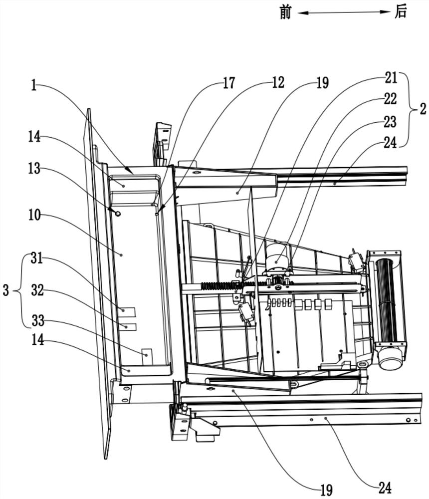
[0049] The technical solutions of the present invention will be further described below in conjunction with the accompanying drawings and through specific implementation methods.

[0050]In the description of the present invention, it should be understood that the orientation or positional relationship indicated by the terms "upper", "lower", "front", "rear" etc. is based on the orientation or positional relationship shown in the drawings, and is only for convenience The present invention is described and simplified descriptions do not indicate or imply that the device or element referred to must have a specific orientation, be constructed and operate in a specific orientation, and thus should not be construed as limiting the present invention. In addition, the terms "first" and "second" are used for descriptive purposes only, and cannot be interpreted as indicating or implying relative importance or implicitly specifying the quantity of indicated technical features. Thus, a f...


PUM


Abstract

A water tank structure comprises a water tank body and a telescopic driving assembly. The telescopic driving assembly is in transmission connection with the water tank body and is used for driving the water tank body to do forward push-out and backward return movement; the water tank body is provided with a water storage tank, and the water storage tank sinks downwards relative to the top end face of the water tank body; a sensor assembly is arranged in the water storage tank, and the sensor assembly is used for detecting the water level in the water storage tank and sending a water level signal to the control chip based on the detected current water level; the telescopic driving assembly comprises an instruction receiving element, and the instruction receiving element is used for receiving an operation instruction of the control chip; and the telescopic driving assembly drives the water tank body to do forward push-out motion according to the operation instruction. The sensor assembly is arranged in the water tank body, the water level of the water storage tank in the water tank body is detected in real time, corresponding water level signal reminding is made according to different water levels, the water level monitoring timeliness of the water tank of the steaming oven is achieved, and the problem that water level detection of the water tank is delayed in the traditional technology is solved.

Description

technical field [0001] The invention relates to the technical field of steam ovens, in particular to a water tank structure and a steam oven assembled therewith. Background technique [0002] With the significant improvement of people's living standards and the continuous upgrading of home appliance technology and functions, kitchen appliances with traditional functions can no longer meet the needs of consumers. Consumers expect kitchen appliances to bring better cooking effects and better use Compared with the traditional steamer, the steam oven with steam function is more and more popular among consumers. During the use of the steaming oven, the generation of steam is inseparable from water, and the steaming oven usually uses a water tank to complete the storage of water, and then uses a water pump to guide the water in the water tank to the heating plate for heating and evaporation, providing high-temperature steam for the cooking space. So as to achieve the function of ...

Claims


Application Information

Patent Timeline
IPC IPC(8): A47J27/04A47J37/06A47J36/00
CPCA47J27/04A47J37/06A47J36/00
Inventor 陈小平张明王成
Owner YUNMI HULIAN TECH (GUANGDONG) CO LTD
Why Eureka
Try Eureka