
Aromatherapy cup with extinguishing module

An aromatherapy cup and aromatherapy technology, which is applied in the parts of lighting devices, dispersed particle filtration, lighting and heating equipment, etc., can solve the problems of choking and difficult to clean.

Pending Publication Date: 2021-05-28
严长和
View PDF0 Cites 0 Cited by
  • Summary
  • Abstract
  • Description
  • Claims
  • Application Information

AI Technical Summary

Problems solved by technology

[0003] 1. Traditional aromatherapy candles generally do not have a stable structure. When the candle is burning, there will be some melted paraffin in the candle cup. If it is spilled on the table, it is difficult to clean up, and if the user does not find it in time, there is still a certain risk of burning candles;
[0004] 2. Every time the candle is extinguished for aromatherapy, people need to get close to the wick of the candle and blow hard to extinguish the candle. After the candle is extinguished, the gaseous wax around the wick solidifies into small wax particles and forms white smoke. Choking

Method used


Image

  • Aromatherapy cup with extinguishing module
  • Aromatherapy cup with extinguishing module
  • Aromatherapy cup with extinguishing module

Examples


Embodiment 1

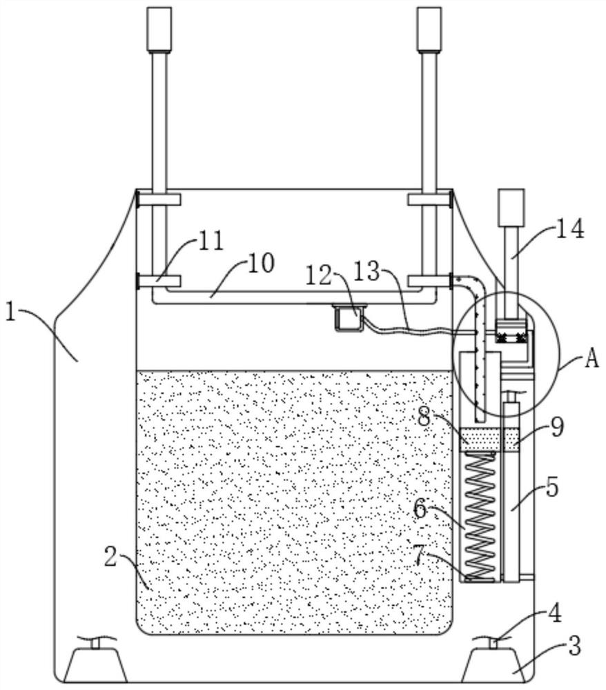
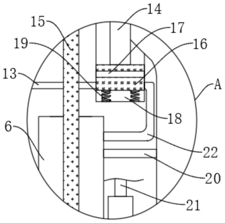
[0026] refer to Figure 1-2 , an aromatherapy cup with an extinguishing module, including a cup body 1, the upper end of the cup body 1 is provided with an installation groove 2, and the cup body 1 is provided with a pressurized chamber 6 and a negative pressure chamber 5, and the pressurized chamber 6 is located in the installation groove 2 The right side of the negative pressure chamber 5 is located on the right side of the booster chamber 6, and the upper end of the cup body 1 is provided with a pressing groove 18;

[0027] The pressurization chamber 6 and the installation groove 2 are jointly provided with a thermal contact module, and the thermal contact module includes a plurality of installation blocks 11 installed on the inner walls of both sides of the installation groove 2, and the adjustment rods 10 are installed on the plurality of installation blocks 11, increasing The pressure chamber 6 is provided with a first magnetic block 8 for sliding up and down. The lower ...

Embodiment 2

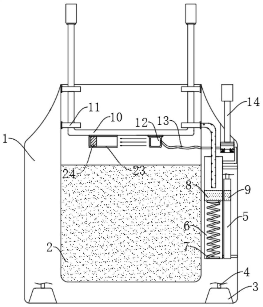
[0038] refer to image 3 , The difference between this embodiment and Embodiment 1 is that a filter box 23 is installed at the lower end of the crossbar, and a through hole 24 is horizontally penetrated in the filter box 23, and a filter element is installed in the through hole 24.

[0039] In this embodiment, after the high-pressure airflow discharged from the air outlet extinguishes the candle, it will continue for a period of time (the user's hand is always pressed on the pressing rod 14). The white smoke is adsorbed to the high-pressure airflow, and then filtered through the filter element in the filter box 23, and then discharged from the left side of the port 24 to completely filter the white smoke.


PUM


Abstract

The invention discloses an aromatherapy cup with an extinguishing module. The aromatherapy cup comprises a cup body, a mounting groove is formed in the upper end of the cup body, a pressurizing cavity and a negative pressure cavity are formed in the cup body, the pressurizing cavity is located at the right side of the mounting groove, the negative pressure cavity is located at the right side of the pressurizing cavity, and a pressing groove is formed in the upper end of the cup body; and a thermal contact module is arranged in the pressurizing cavity and the mounting groove jointly, the thermal contact module comprises a plurality of mounting blocks mounted on the inner walls of the two sides of the mounting groove, an adjusting rod is mounted on the multiple mounting blocks jointly, and a first magnetic block used for sliding up and down is arranged in the pressurizing cavity. In the using process of the aromatherapy cup, a stabilizing structure is arranged, so that the situation that a candle is knocked over during combustion is effectively avoided; and when the candle is extinguished, generated white smoke can be adsorbed, and the situation that people are choked by the white smoke is avoided.

Description

technical field [0001] The invention relates to the field of aromatherapy cups, in particular to an aromatherapy cup with an extinguishing module. Background technique [0002] Aromatherapy candles are a kind of craft candles. They have rich shapes and beautiful colors. The natural plant essential oils contained in them emit a pleasant fragrance when burned. They have the effects of beauty care, soothing nerves, purifying air, and eliminating odors. , but in actual use, scented candles also have the following problems; [0003] 1. Traditional aromatherapy candles generally do not have a stable structure. When the candle is burning, there will be some melted paraffin in the candle cup. If it is spilled on the table, it is difficult to clean up, and if the user does not find it in time, there is still a certain risk of burning candles; [0004] 2. Every time when the candle is extinguished for aromatherapy, people need to get close to the wick of the candle and blow hard to ...

Claims


Application Information

Patent Timeline
IPC IPC(8): F21V35/00A61L9/03B01D46/00
CPCA61L9/03B01D46/0002F21V35/00
Inventor 严长和
Owner 严长和
Learn More