
Drain valve for hydrogen dryer

A technology for dryers and drain valves, applied to valve details, safety valves, balance valves, etc., can solve problems such as fire hazards and hydrogen leakage, and achieve the effects of preventing large amounts of leakage, reducing output speed, and avoiding fire phenomena

Pending Publication Date: 2021-05-28
SUZHOU TAILIDENG PURIFICATION EQUIP
View PDF0 Cites 0 Cited by
  • Summary
  • Abstract
  • Description
  • Claims
  • Application Information

AI Technical Summary

Problems solved by technology

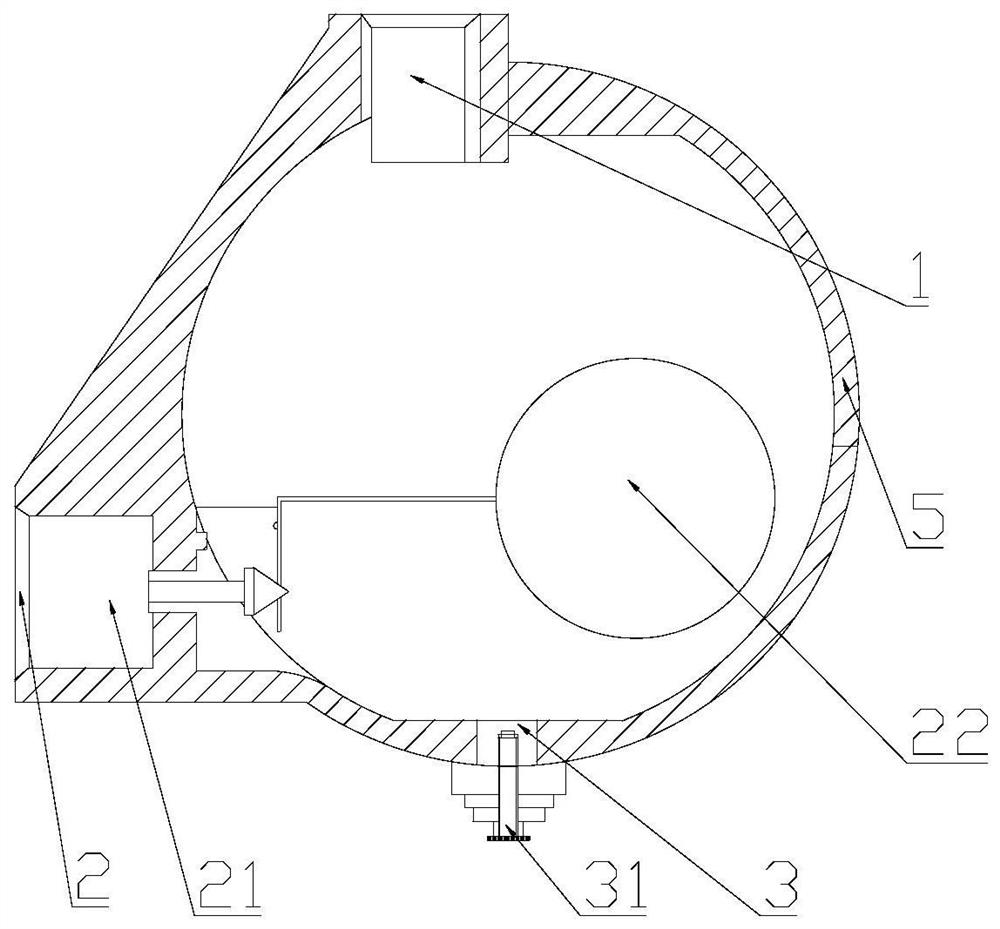
[0002] The specific structure of the traditional drain valve for hydrogen dryer, such as figure 1 As shown, it includes a housing 5, one end of the housing 5 is provided with an inlet 1, one side of the housing 5 is provided with an outlet 2, and a valve 21 is provided in the outlet 2, and a floating ball 22 is provided on the valve 21, and the drain valve has the function of controlling hydrogen drying. The main process is as follows: when the accumulated water in the drain valve reaches a certain height, the floating ball 22 will be pushed to float, and the floating ball 22 will pull the valve 21 to open the drain valve to discharge the accumulated water in the drain valve. After the accumulated water is drained, the floating ball 22 will drop, and the valve 21 will reset to stop the drainage process; but when the valve 21, the floating ball 22 or other sealing mechanisms fail, it will cause a large amount of hydrogen leakage, which is prone to fire

Method used


Image

  • Drain valve for hydrogen dryer
  • Drain valve for hydrogen dryer

Examples


Embodiment Construction

[0014] The technical solutions in the embodiments of the present invention will be clearly and completely described below in conjunction with the accompanying drawings in the embodiments of the present invention. Apparently, the described embodiments are only some of the embodiments of the present invention, not all of them. Based on the embodiments of the present invention, all other embodiments obtained by persons of ordinary skill in the art without creative efforts fall within the protection scope of the present invention.

[0015] The specific implementation manner of the present invention will be further described in detail below in conjunction with the schematic diagrams.

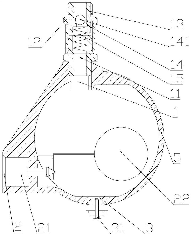
[0016] Such as figure 2 As shown, a drain valve for a hydrogen dryer includes a housing 5, an inlet 1 is provided at one end of the housing 5, an outlet 2 is provided on one side of the housing 5, a valve 21 is provided in the outlet 2, and a valve 21 is provided on the valve 21. There is a floatin...


PUM


Abstract

The invention discloses a drain valve for a hydrogen dryer. The drain valve comprises a shell, an inlet is formed in one end of the shell, an outlet is formed in one side of the shell, a valve body is arranged in the outlet, and a floating ball is arranged on the valve body; a lower shell and an upper shell connected to the outer side face of the lower shell in a sleeving mode are arranged at the inlet, a connector is arranged at one end of the upper shell, a valve element corresponding to the lower shell is arranged in the upper shell, a spring is arranged between the valve element and the lower shell, and a valve bead is arranged on the side face of the valve element. When the sum of the hydrogen pressure in the shell and the elastic force of the spring is greater than the hydrogen pressure in the connector, the valve element moves towards the connector, a gap between the connector and the valve element is reduced, the output speed of hydrogen is reduced, and therefore the hydrogen pressure in the shell is reduced, when the floating ball or the valve body breaks down and accordingly hydrogen leakage occurs, the valve element acts to seal a hydrogen channel, large-amount leakage of hydrogen is prevented, and the fire phenomenon is avoided; and the valve bead can play a role in quantitative drainage, and it is ensured that a leakage stopping device does not affect the drainage capacity of the drain valve.

Description

technical field [0001] The invention relates to accessories of a hydrogen dryer, in particular to a drain valve for a hydrogen dryer. Background technique [0002] The specific structure of the traditional drain valve for hydrogen dryer, such as figure 1 As shown, it includes a housing 5, one end of the housing 5 is provided with an inlet 1, one side of the housing 5 is provided with an outlet 2, and a valve 21 is provided in the outlet 2, and a floating ball 22 is provided on the valve 21, and the drain valve has the function of controlling hydrogen drying. The main process is as follows: when the accumulated water in the drain valve reaches a certain height, the floating ball 22 will be pushed to float, and the floating ball 22 will pull the valve 21 to open the drain valve to discharge the accumulated water in the drain valve. The floating ball 22 will descend after the accumulated water is exhausted, and the valve 21 resets to stop the draining process; but when the val...

Claims


Application Information

Patent Timeline
Patent Type & Authority Applications(China)
IPC IPC(8): F16K31/20F16K31/24F16K17/06F16K17/164F16K27/08
CPCF16K17/0406F16K17/048F16K17/06F16K17/164F16K27/08F16K31/20F16K31/24
Inventor 刘锐张华军岳巍包付海袁文祥封必亮王英冬
Owner SUZHOU TAILIDENG PURIFICATION EQUIP
Learn More