
Telescopic device capable of being rapidly installed

A telescopic device, a fast technology, applied in the erection/assembly of bridges, pavement details, buildings, etc., can solve the problems affecting the service life and maintenance cost of the telescopic device, the long construction period of the installation process, and the difficulty in controlling the welding quality. The effect of maintenance cost, improving service life and reducing production cost

Inactive Publication Date: 2021-05-28
NANJING MAOLE ENG MATERIALS CO LTD
View PDF0 Cites 0 Cited by
  • Summary
  • Abstract
  • Description
  • Claims
  • Application Information

AI Technical Summary

Problems solved by technology

[0008] The construction period of the above-mentioned installation process is long, and a lot of manpower and material resources are required for welding, and the welding quality is difficult to control. The welding quality will directly affect the service life and maintenance cost of the telescopic device after it is put into use.

Method used


Image

  • Telescopic device capable of being rapidly installed
  • Telescopic device capable of being rapidly installed

Examples


Embodiment Construction

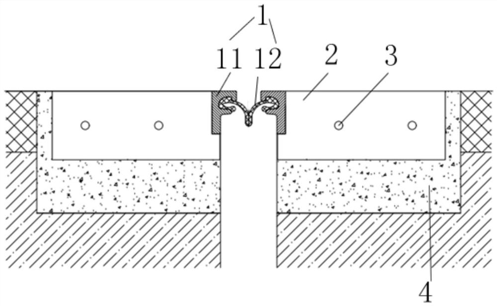
[0028] like Figure 1-2 As shown, a telescopic device that can be quickly installed includes a telescopic device body 1. The telescopic device body 1 includes two side beams 11 arranged symmetrically. The side beams 11 are made of F-shaped steel, and a sealing rubber is connected between the two side beams 11. The bar 12 and the opposite sides of the two side beams 11 are respectively provided with a plurality of long anchor plates 2 distributed side by side at equal distances along the length direction. The top surface of the side beam 11 is flush with the top surface of the long anchor plate 2 . The long anchor plate 2 is provided with several rivets 3 . Compared with the traditional telescopic device, the telescopic device of the present invention does not need welding steps, and can be poured after hoisting and fixing, saving a lot of construction time, manpower, material resources and financial resources.

[0029] Specifically, the long anchor plate 2 is arranged obliqu...


PUM


Abstract

The invention provides a telescopic device capable of being rapidly installed, and particularly relates to the technical field of bridge telescopic devices. The telescopic device comprises a telescopic device body, the telescopic device body comprises two symmetrically arranged boundary beams, the opposite side faces of the two boundary beams are provided with a plurality of long anchor plates distributed side by side in the length direction, and the long anchor plates are provided with a plurality of rivets. The device has the advantages of reducing the construction procedures of the telescopic device and saving the construction cost.

Description

technical field [0001] The invention belongs to the technical field of bridge telescopic devices, in particular to a fast-installable telescopic device. Background technique [0002] At present, the telescopic devices in the prior art generally include symmetrically arranged side beams, and the side beams are provided with a number of anchor rings, and the telescopic devices are installed and fixed by welding the anchor rings with pre-embedded anchors and supporting system towers. The specific installation steps are as follows : [0003] (1) Laying out; [0004] (2) Grooving; [0005] (3) Hoisting of the telescopic device; [0006] (4) Welding and formwork support (anchor rings and embedded anchors and support system towers are firmly welded); [0007] (5) Pouring concrete and curing. [0008] The construction period of the above-mentioned installation process is long, and a large amount of manpower and material resources are required for welding, and the welding qualit...

Claims


Application Information

Patent Timeline
IPC IPC(8): E01D19/06E01D21/00
CPCE01D19/06E01D21/00E01C11/12
Inventor 郑敏霞赵强汤嵩王庆雄
Owner NANJING MAOLE ENG MATERIALS CO LTD
Learn More