Air filtering equipment for textile production

A technology of air filtration and equipment, applied in the fields of dispersed particle filtration, climate change adaptation, climate sustainability, etc., can solve the problems of reduced efficiency, dust shedding, affecting air filtration performance, etc., to ensure air filtration efficiency and strong cleaning ability , easy to use effect

Inactive Publication Date: 2021-05-28
杭州金知科技有限公司
View PDF1 Cites 0 Cited by
  • Summary
  • Abstract
  • Description
  • Claims
  • Application Information

AI Technical Summary

Problems solved by technology

For the dust accumulated outside the filter cartridge during the production process, the reverse air blowing method is usually used, that is, air is blown from the clean air chamber to the filter cartridge, and the pulse blowing method is used to make the filter cartridge vibrate, and the air flows from the filter cartridge Blow it out to make the dust accumulated outside the filter cartridge fall off. Chinese patent 201822071258.7 "a pulse bag filter and pulse bag filter device" also belongs to this category. In occasions where the adhesion is not strong, such as in feed production and stone processing, it is handy to use, but in some dust with relatively strong adhesion, such as in textile production, some small silk threads, yarns, fibers, etc. The force is obviously greater than the small dust particles, so the pulse blowing method is not suitable for the dust removal of the filter cartridge, and once the surface of the filter cartridge is covered by dust, it will obviously affect its air filtration performance and reduce the efficiency

Method used


Image

  • Air filtering equipment for textile production
  • Air filtering equipment for textile production
  • Air filtering equipment for textile production

Examples


Embodiment 1

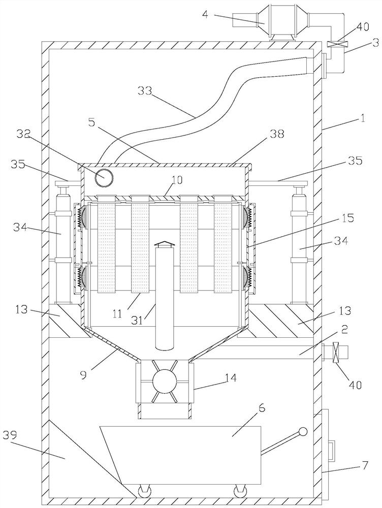
[0034] Such as figure 2 As shown, the air filter equipment for textile production described in this embodiment includes a casing 1, an air inlet pipe 2, an air outlet pipe 3, an exhaust fan 4, an air filter box 5 and an ash truck 6, and the air outlet pipe 3 It is arranged on the upper part of the casing 1 and connected to the exhaust fan 4. The air inlet pipe 2 is arranged on the middle and lower part of the casing 1. The inlet pipe 2 and the air outlet pipe 3 are provided with a valve 40, and the lower part of the casing 1 is provided with an ash outlet. Door 7; the air filter box 5 includes a clean air chamber 8 and an ash hopper 9, and the bottom plate 10 of the clean air chamber 8 is provided with four (or other numbers) filter cartridges 11 for filtering air. The side wall of the clean air chamber 8 has an extension section 12 that exceeds the bottom plate 10 downwards, the ash hopper 9 is connected to the inner wall of the casing 1 through a base 13, and a valve 14 is ...

Embodiment 2

[0048] Such as Figure 6 In order to further improve the filtering effect of the air, the air filtering equipment for textile production described in this embodiment is different from that in Embodiment 1 in that the filter cartridges 11 on the bottom plate of the clean air chamber 8 are arranged in a matrix. In this way, the number of filter cartridges 11 is significantly increased, and the filtering performance can be significantly enhanced.

[0049] Among them, the filter cartridges 11 in embodiment 1 are arranged in a straight line, and the whole air filter box 5 can be made into a cylindrical or square shape at this time, but in this embodiment, due to the increase of the number of filter cartridges 11, the whole air filter box 5 can be made into a square shape .

Embodiment 3

[0051] Such as Figure 7 As shown, this embodiment describes a continuously working air filter device for textile production. The difference from Embodiment 1 is that a bypass pipe 42 is directly connected between the air inlet pipe 2 and the air outlet pipe 3. The upper end and the lower end of the through pipe 42 are provided with a valve 41 , and a backup filter 43 is arranged on the bypass pipe 42 .

[0052] The working method of this air filtering equipment for textile production which can work continuously is mainly to undertake the task of air filtering by the air filtering box 5. During work, the valves 40 on the inlet pipe 2 and the outlet pipe 3 are opened, and the valves on the bypass pipe 42 are opened. The valve 41 is closed to isolate the bypass pipe 42 from the exhaust fan 4;

[0053] When the outer wall of the filter cartridge needs to be cleaned, the valve 40 on the inlet pipe 2 and the outlet pipe 3 is closed, the valve 41 on the bypass pipe 42 is opened, an...


PUM


Abstract

The invention discloses air filtering equipment for textile production, which comprises a shell, an air inlet pipe, an air outlet pipe, an exhaust fan, an air filtering box and an ash discharging vehicle; wherein an annular movable section is arranged between an air purifying chamber and an ash hopper, a first corrugated pipe is arranged between an extension section and the movable section, and a second corrugated pipe is arranged between the movable section and the ash hopper; the outer wall of the extension section is connected with a first outer ring cover, the inner wall of the extension section is connected with a first inner ring cover, the outer wall of the dust hopper is connected with a second outer ring cover, and the inner wall of the dust hopper is connected with a second inner ring cover. The air filtering equipment has the beneficial effects that after the filter cartridge cleaning device works for a period of time, the dust on the surface of the filter cartridge can be removed, dust attached to the outer wall of the filter cartridge is brushed off by a brush arranged on the filter cartridge cleaning ring in a sleeving mode in the ascending process of the filter cartridge, and the cleaning capacity is higher and more thorough; therefore, a good air filtering effect can be achieved on air which is generated in textile production and contains fine silk threads, slivers, fibers, fluff and other impurities with obvious adhesive force.

Description

technical field [0001] The invention relates to a filtering device, in particular to an air filtering device used in textile production. Background technique [0002] In industrial production, in order to purify the environment or ensure the normal and orderly production, air filtration equipment (air filtration equipment) is usually used to purify the air, and the impurities in the air are removed by the principle of filtration. For example, the dust collectors used in some production enterprises adopt the principle of filtration. The existing dust collectors such as figure 1 As shown, it uses the exhaust fan to extract air from the clean air chamber, and takes in air from the air inlet to filter out the dust and impurities in the air outside the filter cartridge, and the clean air is discharged outside through the clean air chamber to achieve the purpose of filtering. The purpose of the air, so that the air after discharge can not affect the environment. For the dust acc...

Claims


Application Information

Patent Timeline
Patent Type & Authority Applications(China)
IPC IPC(8): B01D46/00B01D46/24
CPCB01D46/2411B01D46/681Y02A50/2351
Inventor 不公告发明人
Owner 杭州金知科技有限公司
Why Eureka
Try Eureka